Isolation mounts
Overview
In most applications a means must be provided to mount the ultrasonic stack to a support structure. (Ultrasonic cleaning is one exception where the transducer is attached directly to the walls of the cleaning tank.) Depending on the application, the isolation mount may be attached to the transducer, booster (most common), and/or horn. The support structure could be some type of stand (e.g., for plastic welding) or a housing (e.g., for a hand-held device).
Requirements
- The mount must acoustically isolate the ultrasonic stack. Otherwise, ultrasonic energy will be transferred to the support structure.
— This energy is wasted (can't be applied to the load).
— This energy results in friction which may cause galling of the support structure, heating (e.g., if the housing will be hand–held), or noise. - The mount must allow reasonably precise positioning of the stack's output surface with respect to the load.
- The mount must prevent excessive axial or lateral deflection under the applied loads.
Types
Generally there are two types of mounts — elastomeric and rigid. Elastomeric mounts are those that employs an elastomer (e.g., rubber) for isolation. The most common elastomer shape is an O‑ring. Rigid mounts are those that use all-metal construction. These are used where high rigidity (low deflection under static load) and precise location are required. However, these are more expensive and less forgiving than elastomeric mounts.
O‑ring mounts
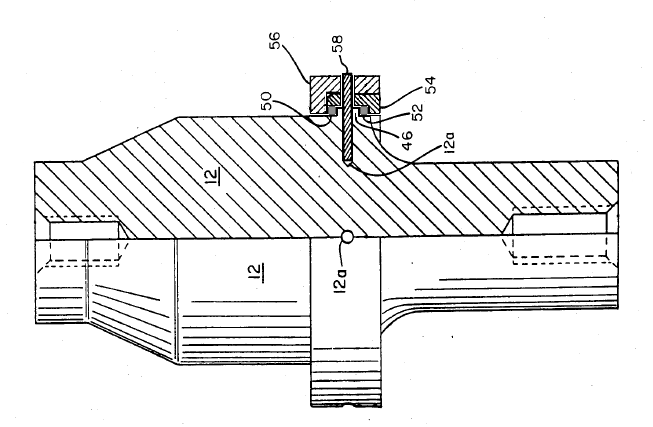
In addition to acoustically isolating the ultrasonic stack, O‑rings provide cushioning during impact loading. Typically, one O‑ring is mounted on each side of a O‑ring flange (figure 1). With approprite tolerances on the O‑ring flange and housing, the O‑rings are compressed slightly as the transducer body is assembled to the housing.
(In this discussion, "housing" is defined as those elements that capture the O‑rings. Thus, for instance, the housing could be rings around the O‑ring flange of a booster or the assembly that encloses a transducer body. In use, the housing is generally clamped in some manner to a support structure.)
|
|
|
|
||||||||||||||||
|
Notes for figure 1 —
- The inner housing ring (54) is pressed into the outer housing ring (56). This compresses the O‑rings against the O‑ring flange (46). Afterwards the antirotation pins (58) are installed.
- Once assembled, the housing can only be disassemblied by disintegrating the pins (e.g., by drilling or EDM). Hence, O‑ring replacement is not realistic.
|
|
|
|
||||||||||||||||||
|
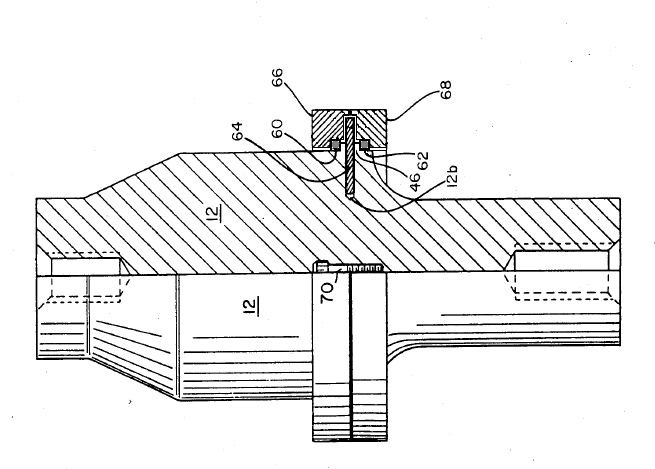
Notes for figure 2 —
- The rear housing ring (66) is secured to the front housing ring (68) with screws (70), typically 6x. This compresses the O‑rings against the O‑ring flange (46).
- The clearance grooves in the housing rings into which the antirotation pins (58) nestle can be machined in the rings with a ball end mill before assembly. Then the antirotation pins must be installed before assembly. Alternately, the clearance grooves can be through-drilled after assembly and the antirotation pins can then be installed.
- This design allows easy O‑ring replacement but is more expensive to machine and assemble than that of figure 1.
Many variations are possible. For example, the inner ring of figure 1 could be a slip fit rather than a press fit. It could then be secured with a snap ring that seats into an inner groove in the outer ring. Groove-slot zzz.
O‑ring specifications
If the O‑ring is subject to compression or impact during the application (e.g., plastic welding) then a material with appropriate tensile strength must be chosen. For example, as a group polyurethane elastomers have high tensile strength whereas silicone elastomers have relatively low tensile strength (Parker (2), p. 2‑6). Coenen patent 4,647,336 suggests Viton fluorocarbon O‑rings with 90 durometer (p. 5, line 5). (Note — In many applications (e.g., plastic welding) only the rear O‑ring is compressed as pressure is applied to the horn's face. Then the front O‑ring can have a significantly lower durometer, if needed.)
After choosing the material, the O‑ring must be sized so that it can repeatedly absorb the loads; generally, higher loads require thicker O‑rings. For example, the transducer of figures 1 and 2 use O‑rings that are 3.5 mm thick. If a second resonator, such as a booster, helps to share the loads with the transducer then the transducer's O‑rings can be thinner.
After the O‑ring has been sized, the dimensions of the lands where the O‑rings seat in the front driver and housing can be adjusted to give the required fits. Generally, these dimensions can be the same as for static fluid sealing applications (Parker (2), section 4) except that the desired static O‑ring compression (below) must be observed. Of course, the O‑ring can be stretched to fit but this should be limited to 5% because the resulting internal stress causes more rapid aging (Parker (2), p. 3‑9).
Note — Square "O‑rings" have been tried. These tests indicated that square "O‑rings" were less effective in isolating the housing from the transducer body. The details of these tests are not known.
Static compression
After assembly the O‑rings must be sufficiently compressed that the housing doesn't "wobble" about the front driver. However, if the O‑rings are excessively compressed then they will transmit ultrasonic energy to the housing. The amount of compression will depend on the durometer of the O‑rings. Also, factors such as compression set, temperature effects, aging, etc. should be considered. (See (Parker (2).)
Coenen patent 4,647,336 suggests 10% compression (p. 5, line 31) when using Viton fluorocarbon O‑rings with 90 durometer (p. 5, line 5). (Coenen doesn't state if this compression is radial, axial, or both.)
For the 20 kHz transducer shown here (figures 1 and 2), the O‑rings are Parker 2‑230 or equivalent (nominal dimensions — 70.15 mm OD x 63.09 mm ID x 3.53 mm thick; Parker (2), p. 9-5). Each O‑ring has nominally zero radial clearance between it and the housing (i.e., a slip fit); this allows easier assembly. After assembly each O‑ring has 11% axial compression which, by Poisson's effect, also results in some radial compression.
Antirotation
Where a housing is required, the housing must be prevented from rotating with respect to the resonator. This maintains proper alignment of the ultrasonic stack with respect to the load (e.g., in plastic welding). In a transducer this also prevents the electrode wires from becoming twisted and possibly breaking. There are two common methods to accomplish this.
- Antirotation pins. See figures 1 and 2. The O‑ring flange is located in the vicinity of the node. It need not be located exactly at the node because the O‑rings can absorb some ultrasonic motion.
Solid pins and split pins have been used. However, under heavy loading where the housing is rigidly supported, the isolation O‑rings may compress excessively and the pins may then contact the clearance holes in the housing. If this occurs repeatedly (as with a plastic welder) and especially under impact, then the pins may fail by fatigue. In this case Spirol® pins are preferred for their superior impact resistance. Spirol® pins also allow looser drill tolerances and have other benefits. - Keyed designs. The resonator and housing may have keys (e.g., flats or splines) that mate with small clearances. These can allow for substantial axial movement between the housing and resonator while still tightly limiting rotation. For example, see the Coenen patent 4,647,336.
Grounding
In a transducer it may be desirable to have the transducer's body electrically grounded to the housing. If other grounding means are not convenient (e.g., because of assembly difficulties) then this ground path can be established by substituting a conductive O‑ring for one of the standard O‑rings. Such O‑rings are available for custom order from Parker Chomerics (3). If corrosion resistance is not important then try CHO‑SEAL 1285 (silver-plated-aluminum filled); otherwise, try CHO‑SEAL 6502 (nickel-aluminum filled). (Contact Parker or similar for specifics.)
Note that the base materials above are silicone which have relatively poor tensile strengths. Hence, if compressive/impact loads are expected then only a single conductive O‑ring should be used and it should be the front one (of the pair) so that its loading is minimal.
Rigid mount
Many rigid mount designs have been proposed. These attach precisely either at a node or antinode. In some cases there may be two attachment locations. For nodal attachment the mount must decouple the resonator's Poisson lateral motion. For antinodal attachment the mount must decouple the resonator's longitudinal motion.
The attachment member (which substitutes for the O‑ring) is generally tuned to the operating frequency; it may vibrate flexurally or, less often, longitudinally.
In the following, the mount is named either by its popularized name or by the inventor's name.
Nodal mounts
Nodal mounts are designed to decouple the resonator's lateral motion due to Poisson cross-coupling; they are not designed to decouple the resonator's longitudinal motion. Hence, these mounts must be positioned precisely at the resonator's node. Otherwise, some of the resonator's longitudinal motion will be imparted to the mount. This presents two difficulties.
- The node may not be suitable for mounting. For example, the transducer's node of figure zzz is located in the ceramics. For other resonators the node may be located in a radius. Although the resonator can be redesigned to reposition its node, this may cause problems for other design parameters such as gain.
- If a series of boosters of different gains are to be designed, then it may be desirable to locate each mounting ring at the same distance from the booster's input surface. (This is only required if the transducer-booster assembly must fit within certain fixed constraints of the support structure — e.g., in a plastic welding stand.) However, even if all boosters have identical dimensions in their back quarter wave section, the nodes will be in different locations depending on the booster's gain. This is because the node becomes a forward-facing "parabola" as material is removed in the front quarter wave section in order to increase the gain; the "parabolic" curvature increases as the gain increases. Hence, this may require some design contortions.
- In some cases the isolation mount is a separate part from the booter body. This reduces material and machining costs compared to a one-piece design. If the two parts are made of the same material then they can often be joined. For example, if both parts are titanium then they can be joined by electron beam welding. However, if the ring were titanium (for strength and to minimize deflection) and if the booster body were aluminum, then joining these dissimilar materials becomes a problem. Although the ring might be pinned to the booster body, the pin holes in the booster would eventually elongate due to impact or bending loads. Of course the booster body could be made of titanium but this might not be convenient for the overall system design (for example, if aluminum is preferred because of its better heat conduction).
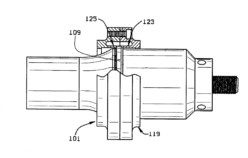
Cunningham mount
Cunningham[2] patent 5590866 (1997).
|
|
|
Antinodal mounts
With the notable exception of the Elmore mount, most antinodal mounts rely on resonant plates or disks (together, "beams") for decoupling. These provide good support for transverse loads but are not as effective for axial loads.
Elmore mount
Elmore[1] patent 2891178 (1959).
Polar mount
|
|
|