Threads and threaded fasteners
Contents
- Figures
- Figure 1. Effect of thread form on fatigue
- Figure 2. Thread fabrication
- Figure 3. Effect of thread fabrication on fatigue life
- Figure 4. Conventional cutting tap and cold-forming tap
- Figure 5. Grain structure — cold-formed thread versus cut thread
- Figure 6. Spiralock threads — load distribution
- Figure 7. Socket set screw, knurled point
- Figure 8. Socket set screw, plain point
- Figure 9. Effect of stud bottom contact on joint temperture
- Figure 10. Effect of stud bottom contact on joint loss
- Figure 13. 3/8-24 integral stud with class R threads
- Figure 14. 1/2-20 integral stud with class R threads
- Figure 11. Washer stud (1/2-20 threads for 20 kHz)
- Figure 12. Washer stud drawing (1/2-20 threads for 20 kHz)
- Tables
- Table 1. Thread root radii (min/max)
- Table 2. Bottomed studs — torques
- Table 3. Loctite® torque performance
Materials
Bolts and studs are often made of high strength steel or titanium. (Stainless steel is occasionally used.)
Ultrasonic transducers may use a titanium center bolt or stud in order to improve electro-mechanical coupling. Titanium studs have been suggested for hardened steel horns in order to reduce failures in the threaded stud hole.
Two sources of titanium bolts and studs are —
Threads
Thread forms
"Standard" threads don't specify a radius at the root of the thread (although small radii will be present due to normal machining practice). These "sharp" roots cause significant stress concentrations which lead to reduced fatigue lives (especially in notch sensitive materials like heat treated steels). Higher hardness ==> larger radius.
In order to improve fatigue life, external threads for studs and screws can specify a root radius. The thread form is specified as UNR or UNJ. Table 1 shows the allowed min/max radii for these threads, together with comparator photographs.
| Table 1. Thread root radii (min/max) |
|
| Thread form |
Min. root radius |
Max. root radius |
Comparator
photograph |
| Standard |
No specification |
No specification |
 |
| UNR |
0.10825p |
0.14434p |
 |
| UNJ |
0.15011p |
0.18042p |
 |
|
Table notes —
- p = thread pitch
- The max. root radius is also the nominal root radius (SPS Technologies[3], p. IV-8).
- Reference for UNR thread form — Kanter[1], p. M-19
- Reference for UNJ thread form — Military Specification MIL-S-8879C, p. 27
- Comparator photographs are from SPS Technologies[3], p. IV-9.
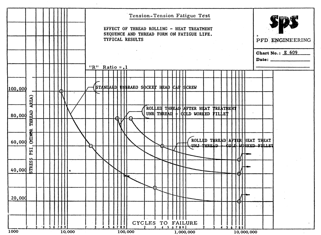
Figure 1 shows the effect on fatigue (Culp[0]). At the runout at 10e6 cycles, the UNR thread form increases the endurance stress from 20 ksi to 40 ksi (+100%) while the UNJ thread form increases the endurance stress from 20 ksi to 50 ksi (+150%).
|
|
| Figure 1. Effect of thread form on fatigue |
|
Important — Fatigue depends on many factors which are not necessarily detailed in these fatigue graphs. Therefore, the data in these fatigue graphs should only be considered as comparison values and should not be used for design purposes.
Thread fabrication
External threads
External threads are fabricated by rolling between dies (for large production lots such as standard socket set screws) or cutting (for small production lots). Cutting removes material and interrupts the natural grain flow. Rolling, which displaces material rather than removing it, gives better fatigue life because it preserves the natural grain flow.
Rolling also improves fatigue strength by inducing compressive stresses at the thread root. However, these compressive stresses are lost if the rolling is followed by heat treatment. Therefore, the threads should be rolled after heat treatment. The disadvantage is that the rolling dies wear more quickly because of the material's increased hardness.
Figure 3 shows the advantage of rolling after heat treatment. At the runout at 10e6 cycles, rolling after heat treatment increases the endurance stress from 20 ksi to 80 ksi (+300%).
Internal threads
Internal threads are needed to accommodate the studs that connect adjacent resonators, for tips, and for the transducer's stack bolt. Because of their high stress concentration, threads can be sites of fatigue crack initiation. Threads are typically fabricated by tapping although special thread forms (e.g., radiused root) may require single point turning.
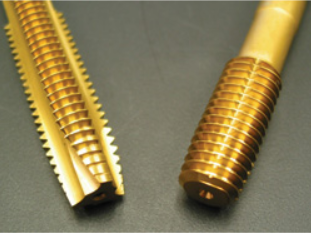
Cold-forming taps
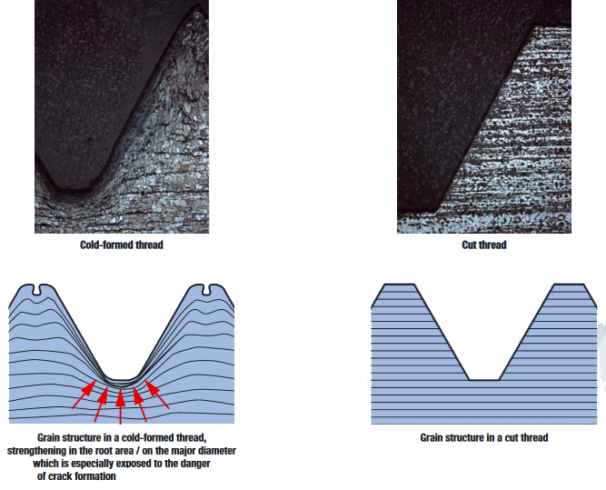
Conventional taps remove material by the cutting action of the tap. However, cold-forming taps have a wedging tooth profile that displaces material rather than removing material. This plastic cold working induces compressive stresses at the thread root while maintaining grain flow and also can leave a radius at the thread root (Figure 5). (Note, however, that the compressive stresses are removed if the part is heat treated after tapping.) Additionally, the thread surface is smooth and burnished (Destefani[1]).
These advantages improve fatigue life. Resistance to static stress also increases. For example, Sağlam[1] (p. 214) reports a 23% increase in average maximum tensile load for M12x1.75 threads with 10 mm of engagement.
Cold-forming taps can be used in softer materials — those with tensile strengths up to 1400 MPa (Emuge[1], p. 19) — including aluminum, Ti-6Al-4V, and some steels (Emuge[1], p. 14).
Compared to conventional tapping, cold-formed tapping can be faster with longer tool life. Also, chip removal isn't a problem because no chips are formed. However, because of the high friction involved in the forming process, special tap coatings and lubricants may be needed (Emuge[1], pp. 4, 24).
|
|
| Figure 4. Conventional cutting tap (left) and cold-forming tap (right) |
|
|
|
Figure 5. Grain structure — cold-formed thread versus cut thread
(Emuge[1], p. 18) |
|
Asymmetric threads
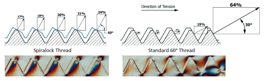
In conventional threads the first few threads absorb the majority of the load; the remaining threads contribute little (the right panel of Figure 6). The load can be more evenly distributed by using an asymmetric thread such as the Spiralock.
|
|
| Figure 6. Spiralock threads — load distribution |
|
Studs
Two adjacent resonators are joined together by a stud. The stud may be a separate entity (discussed here) or may be integral to one of the resonators.
Materials and sizes
Studs are generally made of high strength steel but sometimes of titanium. Stainless steel studs have also been used.
Common sizes are 1/2-20, 3/8-24, and M8. Other sizes may be used depending on a manufacturer's preferences.
Installation
The stud must be secured in one of the two adjacent resonators. Otherwise, the stud may rotate when the joint is either tightened or loosened. Also, the stud must be prevented from migrating within the threaded hole when ultrasonics are activated. Two methods are used — a bottomed stud or an unbottomed (floated) stud.
Bottomed stud
A bottomed stud is commonly used so it is described first. However, it may have problems with heating and loss and, therefore, may not be recommended. (See the discussion of threadlocking adhesives.) Additionally it may cause high static stress at the bottom of the stud hole. This static stress, when combined with the ultrasonic stress, may cause early fatigue failure, particularly for aluminum horns which have a low endurance limit.
There are two methods of bottoming — fully bottomed and wedged. It is not clear if either is superior.
Fully bottomed
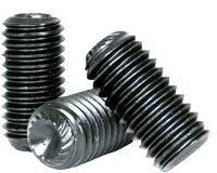
In the fully bottomed method the hole is finished with a bottoming tap. Then the stud is torqued against the bottom of the hole. The stud may have a knurled end to prevent it from loosening. (In figure 7, note that the knurl is on the exterior of the cone. Such screws are available from Unbrako.) Branson Ultrasonics uses this method.
|
|
| Figure 7. Socket set screw, knurled point |
|
Wedged
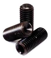
In the wedged method the hole is finished with a tap that leaves several unfinished threads at the bottom of the hole. When the stud is torqued into the hole, its leading edge wedges into these unfinished threads. Dukane likely uses this method.
|
|
| Figure 8. Socket set screw, plain point |
|
Torques
Table 2 shows the recommended torques of several ultrasonic companies. Note the large differences in recommended torques between Branson and Dukane for the same stud size. Some of these torque differences may be attributed to the different end configurations of the studs and the method of bottoming. However, the torque differences are so large that they may indicate some fundamental misunderstanding of the torque requirements.
| Table 2. Bottomed studs — torques |
|
| Stud size |
Ultrasonic company |
Recommended
torque (Nm) |
| 1/2-20 |
Branson Ultrasonics
Patsonics |
51 |
| Dukane |
1.4 - 2.0 |
| Sonics & Materials |
61 |
| 3/8-24 |
Branson Ultrasonics
Patsonics |
33 |
| Dukane |
1.4 - 2.0 |
| M8-1.25 |
Branson Ultrasonics
Patsonics |
7.9 |
| Dukane |
1.4 - 2.0 |
| 1/2-20 to 3/8-24 step stud
| Branson Ultrasonics
| 28
|
|
Table notes —
- References —
- Branson Ultrasonics[2] (p. 4) —"Failure to follow these torque specifications
may result in the horn/booster stud loosening, stud breakage, and
unexplained overloads." Branson notes that a stud that has been used in an aluminum resonator can be reused if the aluminum bits are cleaned from the knurled end. However, a stud that has been used in a titanium resonator (and, presumably, a steel resonator) should not be reused because the knurls will have been damaged which will prevent the stud from locking in the bottom of the hole.
The stud is bottomed in a hole that has been bottom tapped. Culp[0].
- Patsonics[1]
- Dukane[1] (p. 12) — Dukane's studs have a cup point. The stud is wedged in a hole that has not been bottom tapped.
- Sonics & Materials[2] (p. 13)
Unless otherwise noted, the stud torque is the same for horns and boosters, regardless if the resonator material is aluminum, titanium, or steel.
Unbottomed (floated) stud
For an unbottomed (floated) stud, the end of the stud does not touch the bottom of the threaded hole (typically backed off 1/2 turn). Since the stud is unbottomed, some means is needed to prevent it from turning freely in the threaded hole.
Threadlocking adhesives
A threadlocking adhesive is applied to threads and is typically designed to cure anaerobically after the threaded parts have been assembled. Loctite® is one prominent brand although many others are available.
Application to an unbottomed stud
The following procedure is recommended when using a threadlocking adhesive with an unbottomed stud —
- Clean the stud and stud hole thoroughly to remove any oil and contaminates. Otherwise, the thread locking compound will not adhere properly. (Some threadlocking adhesives are somewhat tolerant of oil and contaminates. Consult the manufacturer.)
- Apply the threadlocking adhesive to the resonator threads.
- Hand bottom the stud in the hole and then back off 1/2 turn.
- While preventing the stud from rotating, run a jam nut over the exposed stud until the nut contacts the resonator. Securely tighten the jam nut. (Note — the faces of the jam nut must be very perpendicular to the jam nut's threads. This will assure that the stud remains perpendicular to the resonator's stud surface until the thread locking compound has cured. If a correctly machined jam nut is not available then a threading die works well.)
- After the threadlocking adhesive has cured, remove the jam nut.
- Remove any exposed uncured threadlocking adhesive.
Although Branson uses studs with knurled ends that are bottomed, it may also combine this with Loctite® 290 (where appropriate). A company that makes ultrasonic metal welders uses unbottomed studs with Loctite® 243 (Culp[0]).
Table 3 shows a comparison of these Loctite® grades.
| Table 3. Loctite® torque performance |
|
| Loctite® grade |
Breakaway torque
(Nm) |
Prevailing torque
(Nm) |
Breakloose torque
(Nm) |
| 243 |
20 |
7 |
24 |
| 290 |
10 |
29 |
30 |
|
Table notes —
- The torques are for M10 steel nuts and bolts. The values are for comparison purposes. See the above linked data sheets.
- Breakaway torque — for an unbottomed fastener, the torque required to break the threadlock bond
- Prevailing torque — for an unbottomed fastener, the torque required to continue to rotate the fastener after the threadlock bond has initially been broken
- Breakloose torque — for a bottomed fastener, the torque required to unbottom the fastener
Deformed stud thread
The stud thread can be deformed in some manner so that it interfers with the mating resonator thread. For example, the thread crests can be flattened in a vise or press. The deformation of the stud threads should only be enough to keep the stud from freely moving in the resonator; otherwise, the mating threads of the resonator may be destroyed as the stud is installed. Compared to using a threadlocking adhesive, this method doesn't involve any secondary material, cure time, or chance that the threadlocking adhesive might deteriorate over time.
Bottomed versus unbottomed (floated) studs
Generally, studs should not be bottomed in the stud hole because this causes high static stress at the bottom of the stud hole (particularly a problem for aluminum horns) and also causes heating. Culp[0] conducted tests on the effect of stud bottoming. The test procedure was —
- Tighten the stud "very tight" (no specified torque) into the bottom of the threaded hole. The stud was not disturbed thereafter.
- Apply a thin layer of Molykote grease to the transducer face and tighten the horn to the transducer. (This was done for each test to reduce the possibility that a corrupted joint might contaminate the results.)
- Run the assembly for eight minutes at full amplitude, taking temperature mesurements approximately every two minutes.
- Allow the assembly to cool to room temperature.
- Remove the horn from the transducer.
- Repeat steps 2 through 5 for a total of three tests.
After the above tests were completed for the bottomed stud, the stud was backed off 1/2 turn from the bottom of the threaded hole. The above procedure was then repeated for the unbottomed stud.
Test notes —
- The horn was a 40 kHz high gain half-wave unslotted cylindrical aluminum horn that was attached directly to a transducer (no booster).
- The horn's stud hole was bottom-tapped and the stud was fully bottomed.
- The stud was M8 steel with a knurled point. It was secured in the horn with Loctite grade 242 thread lock regardless of whether it was bottomed.
- The same horn and transducer stack were used for all tests.
- The stack wasn't cooled during the tests .
- The temperatures were measured with a thermocouple on the transducer's aluminum front driver just next to the transducer-horn joint.
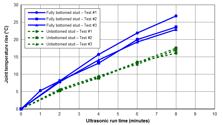
Figure 9 shows the results for three tests each with fully bottomed and unbottomed studs. The temperature advantage of an unbottomed stud is clearly evident. In addition, the data scatter for the unbottomed stud is lower. For corroboration, the average measured power loss for the stack with the unbottomed stud was 37% lower than the bottomed stud. (Note — The unbottomed stud reduced the horn's amplitude by 6.3%. FEA predicts a reduction of 5.2%.)
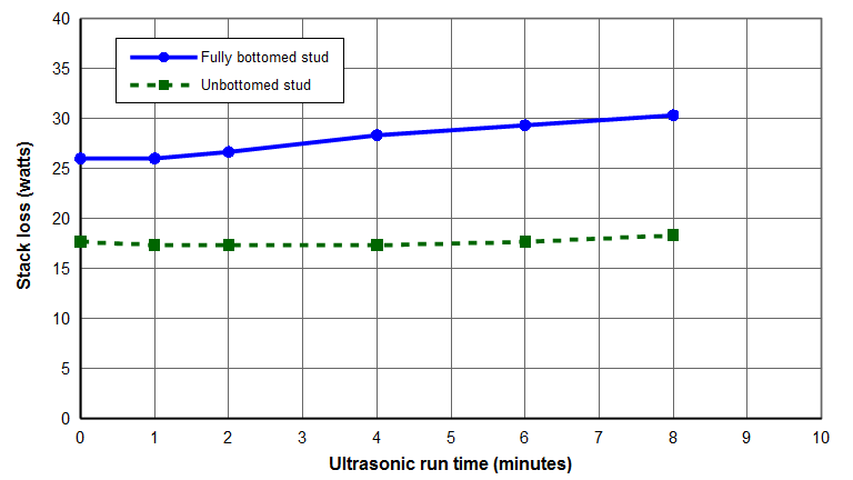
As corroboration, figure 10 shows that the stack loss for the fully bottomed stud was significantly higher than for the unbottomed stud. (Each curve is the average of the three corresponding tests.) In addition, figure 10 shows that the loss for the unbottomed stud was relatively stable throughout the test whereas the loss for the fully bottomed stud increased.
As noted, the bottomed stud was fully bottomed (not wedged). The tests should be repeated for wedged studs.
|
|
| Figure 9. Effect of stud bottom contact on joint temperture |
|
|
|
| Figure 10. Effect of stud bottom contact on stack loss |
|
Also see Integral studs and Washer studs.
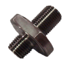
Washer studs
Washer studs replace conventional studs. Washer studs are made of titanium and are typically used between the booster and horn or in composite horns between the mother horn and tip horn.
These have been reported to be effective in certain unspecified situations, possibly due to the reduced joint contact area or because they don't bottom in the threaded hole. Because the washer section has appreciable thickness, at least one of the connected resonators must be tuned to accommodate this thickness. Washer studs have been used by Branson Ultrasonics.
|
|
Figure 11. Washer stud (1/2-20 threads for 20 kHz)
(Culp[0]) |
|
|
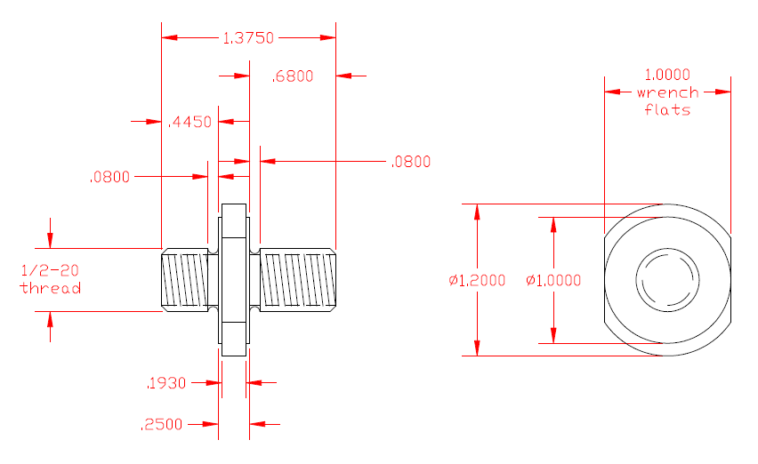
|
Figure 12. Washer stud drawing (1/2-20 threads for 20 kHz)
(Culp[0]) |
|
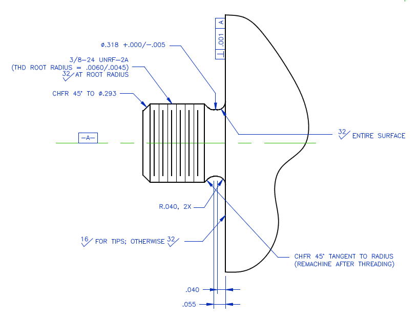
Integral studs
An integral stud is machined as an integral part of a resonator. It is used on tips and often used on small diameter medical probes. It eliminates the need for a separate stud and associated assembly, assures maximum perpendicularity to the associated joint, and minimizes frictional loss and stress that may be caused by a separate stud. It also allows control of the thread form — e.g., UNR or UNJ threads with larger root radii can be specified, if desired. This may be appropriate, for example, for steel horns where the threads may be notch sensitive after heat treatment.
|
|
Figure 13. 3/8-24 integral stud with class R threads
(Culp[0]) |
|
|
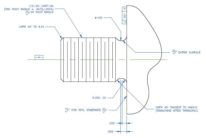
|
Figure 14. 1/2-20 integral stud with class R threads
(Culp[0]) |
|
Integral studs are most suitable for resonators with relatively small lateral dimensions. They are not suitable for resonators with large lateral dimensions since significant material must be machined away in order to create the stud. They also may not be suitable for aluminum resonators since the aluminum thread material may not be sufficiently strong.
Thread failures in steel horns
Steel horns are known to fail in the threads. This is likely due to the notch sensitivity after heat treatment. The following remedies have been suggested or tried.
- Don't bottom the stud. A bottomed stud places a tensile stress on the threads which reduces fatigue life.
- Use a titanium stud. After steel horns have been used for some time, the steel studs show fretting on the thread flanks. Since titanium has half the modulus of steel it may be able to deform under ultrasonic stress without fretting.
- Increase the horn's gain. This will reduce the horn's input amplitude, theregy reducing the ultrasonic stress in the threads.
- Use an integral stud. Rather than having a separate stud, the stud is machined as an integral part of the horn. Then the thread form can be closely controlled.
- Use a different horn material. For example, if wear resistance is needed then try an aluminum or titanium horn with a wear-surface (e.g., chrome, D-gun, carbide). However, if impact resistance is needed then a relatively thin coating like chrome or D-gun might not be suitable.
Effect on horn stress and amplitude
Thread inserts (Helicoil, etc.)