Shear mode horn
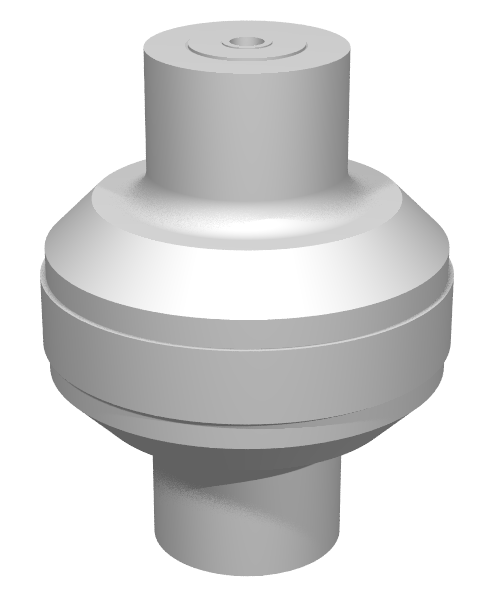
The following is an example of a horn that operates in a shearing mode where the node is a cylinder concentric to the stud axis. (Contrast this with a longitudinal resonator where the node is a plane that is generally perpendicular to the stud axis.)
|
||||||||||
|
Application — Ultrasonic additive manufacturing (UAM)
A similar design has been used in ultrasonic additive manufacturing (see White patent). The horn is supported with booster at each end. The horn rotates and simultaneously traverses a thin strip of welding material, thereby welding the strip to the underlying structure.
Note: Graff (1) uses an alternate shear mode horn design that does not require supporting boosters.
For UAM the peripheral welding surface must be roughened; the type and degree of roughness must be determined experimentally.
Because of the shear scrubbing motion the welding surface will eventually wear, especially when welding harder materials. If the horn amplitude is sufficiently low then the horn could made of steel instead of titanium. Alternately, a wear coating could be applied to the titanium horn (see, for instance, D-Gun). Such a coating might also supply the required roughness.
Design
- The material for this particular horn is Ti-6Al-4V. Assumed material properties —
E = 121.9 GPa
Density = 4425 kg/m³
Poissons ratio = 0.34 - At 20 kHz the horn length is 190 mm and the diameter is 146 mm. The large diameter allows clearance between the peripheral shear welding area and adjacent supporting equipment.
- Tuning — Tune equally from each end. The tuning rate is ~120 Hz/mm at each end.
Performance
- The gain is 0.7.
- The maximum von Mises stress for titanium (8.4 MPa/(micron_peak at the welding surface)) occurs where the node exits into the 10 mm radius.
- The welding surface has 2% rocking motion (compared to its shearing motion). Rocking appears to be minimized when the input and output cylinders have approximately the same diameter as the shear node. Rocking increases as the 17 mm chamfer is decreased.
- Closest adjacent resonances (excluding bending modes) — 18457 Hz, 23874 Hz