Gain
Contents
Definition
In general (for any system):
\begin{align} \label{eq:10501a} \textsf{Gain} = \frac{\textsf{Output}}{\textsf{Input}} \end{align}
For ultrasonic resonators the gain indicates an amplitude ratio:
\begin{align} \label{eq:10502a} \textsf{Gain} = \frac{\textsf{Output amplitude}}{\textsf{Input amplitude}} \end{align}
or, sometimes, a velocity ratio:
\begin{align} \label{eq:10503a} \textsf{Gain} = \frac{\textsf{Output velocity}}{\textsf{Input velocity}} \end{align}
For a given resonator, equations \eqref{eq:10502a} and \eqref{eq:10503a} give the same value.
Unless otherwise specified:
- All amplitudes are in the primary (desired) directions.
- For an axial resonator the relevant amplitudes are the axial amplitudes.
- For a radial disk resonator the input amplitude may be either radial or axial, depending on the design. The output amplitude is the radial amplitude at the periphery of the disk.
- For a flexure resonator the input amplitude is axial. The output amplitude is the flexure amplitude.
- The output amplitude is measured at the center of the face.
- The input amplitude is measured at the center of the stud surface.
If a resonator is said to have gain but no specific value is mentioned, the gain is assumed to be greater than 1.0 (i.e., forward gain). (If the gain is less than 1.0 then the resonator is said to have reverse gain.)
Theory
For any vibrating system that is not acted upon by external forces, momentum must be conserved. For a simple axial resonator for which any transverse motion can be neglected ...
For a halfwave resonator with a sharp step exactly at the node and for which the input section and output section is each prismatic (constant cross-sectional area) and which is made of a single material, the theoretical gain is just the ratio of the output area to the input area.
\begin{align} \label{eq:10507a} {\textsf{Gain}}_{\textsf{theoretical}} = \textsf{Area ratio} \end{align}
where —
\begin{align} \label{eq:10508a} \textsf{Area ratio} &= \frac{\textsf{Area of input surface}}{\textsf{Area of output surface}} \end{align}
Limitations
The definition of gain only considers amplitudes in the primary directions. Then for an axial resonator the calculated gain doesn't account for transverse motion. However, such transverse motion may be significant to the application. For example, many bell horns have appreciable transverse motion. This motion can be helpful for cavitation or defoaming. However, it can be detrimental for plastic welding since it can cause marking of the part (with associated excessive power consumption) and poor welds. Also, such transverse motion can add significant additional stress. Hence, resonators can't be directly compared based solely on their gains.
Composite horns.
Preference for higher gain horns
For two horns that have the same output areas, it can be shown that the horn with the higher gain will have lower energy storage, despite having more mass. (See appendix zzz.) Thus, for large horns that are difficult to start, a higher gain horn will be preferred.
For a given output amplitude a higher gain horn will require lower input amplitude. This means that the hornbooster joint will have lower stress and will last longer before reconditioning is needed. This also means that a lower gain (lower stress) booster can be used so that perhaps the booster can be made from aluminum instead of titanium.
Measurement
Ti Std horn. Intermediate feedback xdu.
For some horns (e.g., those with face cavities such as bell horns), amplitude measurement at the center of the horn face may not be possible. In other cases, the gain may preferably be specified at another location. For example, if a horn is only designed to weld around the periphery of its face then it would make most sense to measure the output amplitude in this peripheral area, even though the center of the horn face might be available. In such cases, the location of the gain measurement must be specified (e.g., \( G_{periphery} \)).
Effect of frequency
Estimating gains for unslotted stepped horns
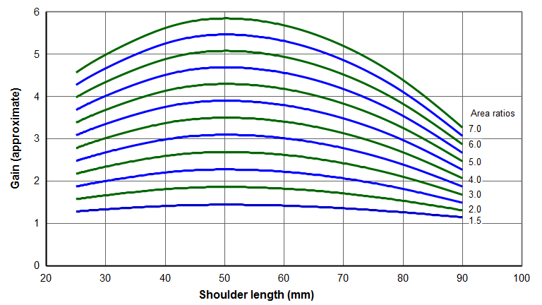
The following graphs show the approximate gains for 20 kHz unslotted horns which have a 40 mm transition radius between the input section and output section. The input section and output section is each prismatic. The values adjacent to the curves are the area ratios. As shown by equation \eqref{eq:10507a} these are also the theoretical gains for a horn with a sharp step (no radius) exactly at the node.
These graphs are applicable to typical acoustic materials (those with a wave speed in the vicinity of 5000 m/sec — e.g., aluminum, titanium, steel). These graphs are suitable for preliminary horn designs. However, note that stresses are not considered.
The graphs are suitable for other frequencies as long as the shoulder length and transition radius are suitably scaled.
Unslotted cylindrical horns
For a cylindrical horn, the \( Area~ratio \) is just the ratio of the input to output diameters.
\begin{align} \label{eq:10504a} Area~ratio &= \frac{{D_i}^2} {{D_o}^2} \end{align}
where —
| \( D_i \) | = Diameter of the input section |
| \( D_o \) | = Diameter of the output section |
|
|
|

Note that the peak gain occurs for shoulder lengths of about 50 mm. In this region the gain curves are fairly flat so a small change in the shoulder length will not significantly affect the gain. Also note that the maximum gain for each design is less than the theoretical gain (the area ratios) due to the effect of the transition radius.
Example
Assume that the following are known —
- Transducer amplitude = 20 microns
- Booster = 1.5:1
- Required horn output = 150 microns
- Horn shape = cylindrical unslotted
- Horn output diameter = 15 mm (as required by the application)
The output amplitude from the booster (which is the input amplitude to the horn) is 20 microns * 1.5 = 30 microns. Since the horn output must be 110 microns the required horn gain is 150/30 = 5.0. Starting with a gain of 5.0 on the vertical axis of the above graph and reading across to find the curve points that intersect the 5.0 gain, the combinations of table 1 are possible. Knowing the acceptable area ratios, the input diameters can be calculated from equation \eqref{eq:10504a} —
\begin{align} \label{eq:10506a} D_i = D_o \sqrt{Area~ratio} \end{align}
|
||||||||||||||||
|
For an area ratio of 6.0 the gain is relatively insensitive to the shoulder length. For example, shoulder lengths between 45 mm and 55 mm have almost no effect on the gain. Even for a shoulder length of 40 mm the gain drops only 4%; for a shoulder length of 60 mm the gain drops only 2%. This means that, if needed, some tuning could occur by adjusting the shoulder position with adversely affecting the gain. For an area ratio of 7.0 the gain is more sensitive to the shoulder length.
Unslotted bar horns
The following graph applies to unslotted stepped bar horns. It is also approximately valid for slotted bar horns without risers. (Risers generally increase the gain.) The values adjacent to the curves are the area ratios.
For a bar horn (for which the input and output widths are equal), the \( Area~ratio \) is just the ratio of the input to output thicknesses.
\begin{align} \label{eq:10505a} Area~ratio &= \frac{T_i} {T_o} \end{align}
where —
| \( T_i \) | = Thickness of the input section |
| \( T_o \) | = Thickness of the output section |
|
|
|
Boosters
Boosters are often color coded by anodizing to indicate the nominal gain. However, the gain may only be nominal. The following are used by several manufacturers —
| Color | Gain |
|---|---|
| Blue | 0.5 |
| Purple | 0.6 |
| Green | 1.0 |
| Gold | 1.5 |
| Silver | 2.0 |
| Black | 2.5 |