Slot optimization - Under development
Contents
- Introduction
- Standard slots
- Advantages of reduced slot stress
- Advanced slots
- Optimization
- Application to other horns
- Figures
- Figure 1. Figure_title
- Tables
- Table 1. Table_title
Introduction
As the lateral dimensions of horns become large (relative to the thin-wire half wavelength), Poisson coupling near the node distorts the face amplitude. If the lateral dimensions become sufficiently large then the longitudinal resonance may disappear entirely — nodes will appear on the face and/or stud surfaces.
To alleviate this problem, wide horns have slots that are aligned parallel to the direction of longitudinal vibration. The slot length is a considerable portion of the half wavelength.
Unfortunately, these slots introduce stress concentrations which may cause fatigue failures toward slot starts.
Standard slots
At 20 kHz the slots are typically 10 mm wide with a full 5 mm radius at each end. (Wider slots 12–13 mm can be used but these may cause performance problems.) Toward the horn's output face the slot web length is typically between 12 mm and 20 mm. Toward the horn's input surface the slot web may be considerably larger if the horn is designed with gain.
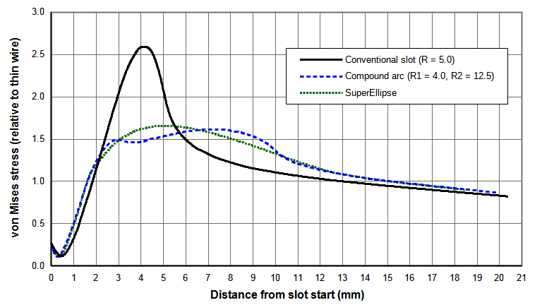
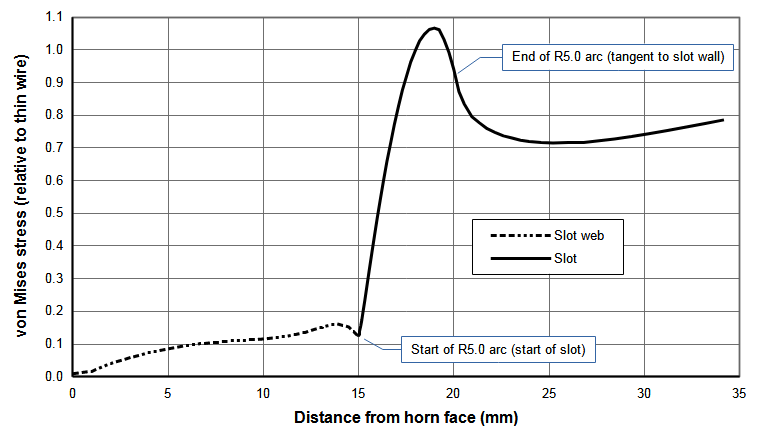
Figure 1 shows the slot stress distribution in a 20 kHz 75 mm wide x 13 mm thick bar horn. (The slot is 10 mm wide with a full 5 mm radius at the start. The web length is 15 mm.) Note the gradual stress rise from the horn's face and then the sudden stress increase at the slot. The stress peaks at 4.1 mm just before the slot arc becomes tangent to the slot wall.
Important — Unless otherwise noted —
- Slot stresses may be normalized in either or both of two manners —
- Normalized with respect to the highest stress in a conventional slot. This shows the relative improvement of the redesigned slot compared to a conventional slot.
- Normalized with respect to the highest (nodal) stress in a longitudinally resonant thin wire. The thin wire is made of the same material and has the same output amplitude as the actual horn. Figure 1 shows a normalized stress curve. Here the maximum value of the relative stress curve is 1.07. This means that the maximum slot stress is 7% higher than the highest stress in a longitudinally resonant thin wire. This allows for comparison of various slot designs that are independent of the horn's material, amplitude, and frequency.
- All dimensions are for 20 kHz horns. However, these can easily be scaled to other frequencies.
- \( X \) dimensions are parallel to the slot axis (i.e., in the direction of axial vibration). (In the FEA models this is the \( Z \) axis.) \( Y \) dimensions are transverse to the slot axis (in the direction of the slot width).
|
|
|
Advantages of reduced slot stress
Reducing the slot stress may have several advantages —
- The horn life may be extended at the current amplitude.
- The existing horn can be run at a higher amplitude without failure.
- The slot web can be increased (i.e., reduced slot length) which may improve the horn's performance (better frequency separation, better amplitude uniformity, reduced transverse amplitude). This will depend on the particular horn design.
The disadvantage is that machining becomes more complex and possibly more somewhat more costly.
Advanced slots
In order to overcome the stress limitations of standard slots, slots with different termination geometries have been optimized with finite element analysis. The investigated geometries include compound arcs, various ellipses, catenaries, and keyholes. Other geometries are possible but may not yield significant improvements. In some cases (e.g., keyholes) the stresses were actually significantly worse.
Design considerations
The slot design was constrained by machining considerations.
- The slots should be machinable using conventional rotary tools. (CNC capability was assumed but not absolutely required.) Then these slots could be machined by most small shops. This criterion eliminated some potential slot geometries (e.g., a slot with a pointed end) that could have been machined by wire EDM or broaching.
- The machining should not depend on the horn material. This eliminated broaching which isn't particularly suited to titanium.
- The machining should not reduce the fatigue life of the horn compared to optimal machining practices. This would usually eliminate EDM.
- The slots should be machinable to considerable depths such as in large slotted block horns. This requires that the machine tool (e.g., end mill) should be as rigid as possible (i.e., large diameter).
Based on the above criteria, the main slot walls (between the optimized terminations) should be machined with a Ø10.0 mm tool. A Ø8.0 mm tool was chosen to machine the optimized slot terminations. (A Ø6.0 mm tool was investigated but didn't give better results.)
In addition, the developed slot design should be suitable for many different horn designs, even though it may not be quite optimal for every horn design.
Optimization
Slots were optimized for a 20 kHz 75 mm wide x 13 mm thick bar horn with a single center slot. R10 mm flutes were added to the ends to give uniform face amplitudes (within ±2%); hence, this horn has essentially axial motion near the slot. This horn also has good frequency separation. (A horn of this width would typically not need a slot. This horn was chosen as a test case based on its simplicity and good performance.)
After optimizing with the above horn, the optimal slots were tested on other horns, in particular a 20 kHz 125 mm x 125 mm cross-slotted block horn.
Compound arcs
The standard 5 mm terminating arc can be replaced with two tangential arcs — a smaller arc with radius \( R_{1} \) at the slot start and a larger connecting arc with radius \( R_{2} \) that transitions from the smaller arc to a tangential termination at the slot wall (i.e., at a slot width of 10 mm). The two arcs are tangent to each other where they meet.
The required value of \( R_{2} \) is given by —
\begin{align} \label{eq:11500a} R_{2} = \frac{Y^2 - R_{1}^2 + (X_{w} - R_{1})^2}{2*(Y - R_{1})}\end{align}
where —
| \( R_{2} \) | = radius of the large connecting arc |
| \( R_{1} \) | = radius of the small arc at slot start |
| \( X_{w} \) | = distance from the slot start to the point where the large connecting arc intersects the slot wall |
| \( Y \) | = 1/2 of the slot width |
Note that \( X_{w} \) is also the distance from the slot start to the centerline of the large connecting arc.
The point \( (X_{t},Y_{t}) \) where the small and large arcs are tangent to each other is given by —
\begin{align} \label{eq:11510a} X_{t} = R_{1}*\sin\left( \theta \right)\end{align}
\begin{align} \label{eq:11520a} Y_{t} = R_{1}*\left\lgroup 1 - \cos\left( \theta \right) \right\rgroup\end{align}
where \( \theta \) is the angle of the small radius \( R_{1} \) at the tangency point \( (X_{t},Y_{t}) \) with respect to the slot axis —
\begin{align} \label{eq:11530a} \theta = \sin^{-1}\left(\frac{R_{2} - Y}{R_{2} - R_{1}}\right)\end{align}
In the above equations, the \( (X,Y) \) coordinate system is located at the slot start with the \( X \) axis aligned with the slot axis and the \( Y \) axis perpendicular to the slot axis.
The general approach is —
- Choose \( R_{1} \) and \( Y \).
- Choose \( X_{w} \) within a reasonable range (must be greater than \( Y \)).
- Calculate \( R_{2} \) based on the above parameters.
- Build the FEA model and analyze the slot stresses.
- Repeat above to find optimal parameters.
Example 1
Assume the following values —
| \( R_{1} \) | = 4 mm |
| \( Y \) | = 5 mm |
| \( X_{w} \) | = 10 mm |
Then the required connecting radius \( R_{2} \) is 22.5 mm. The tangent point between the small and large arcs occurs at \( (X,Y) \) = (3.784,2.703) where \( \theta \) = 71.075°.
Figure 2 shows the stress results for a 10 mm wide slot with \( R_{1} \) = 4 mm and several \( X_{w} \) and associated \( R_{2} \). Table 1 gives the associated slot parameters. \( R_{2} \) = 12.5 mm gives the best overall results.
|
||||||||||||||||||||||||||||||||||||
|
Effect of web length
The slot has been optimized for a 15 mm long slot web. However, analyses at other slot web lengths shows that the performance remains good. Figure N(a) shows the slot stresses for three different web lengths. As expected, as the web length increases (i.e., the slot length decreases) the slot stress also increases since the slot starts closer to the node where the thin-wire stess is highest. Figure N(b) shows the data from figure 1(a) but in this case the stresses of each slot have been normalized with respect to a conventional slot with the same web length. Regardless of the web length, each slot has essentially identical stresses within the R4 mm small arc. Within the region of the large arc there is some stress variation among the slot web lengths but nothing substantial. In fact, the stresses for the 20 mm web length are actually somewhat better. Hence, the slot that was optimized for the 15 mm web length can be used for other web lengths.
|
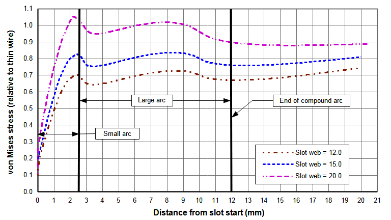
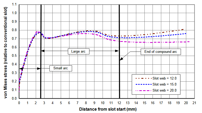
| Figure N. Effect of web length on slot stresses for compound radii (20 kHz 75 mm wide bar horn with one 10 mm wide slot) |
Ellipses
Ellipses of varying degrees are described by the following equation (see SuperEllipse) —
\begin{align} \label{eq:11590a} {{\huge\lgroup}{\frac{z - z_{0}}{a}}{\huge\rgroup}}^p + {{\huge\lgroup}{\frac{y - y_{0}}{b}}{\huge\rgroup}}^q = 1\end{align}
where —
| \( X \) | = curve coordinate along major ellipse axis |
| \( y \) | = curve coordinate along minor ellipse axis |
| \( z_{0}, y_{0} \) | = coordinates of the ellipse center |
| \( a \) | = radius of major ellipse span |
| \( b \) | = radius of minor ellipse span |
| \( p, q \) | = determines the curvatures ("squareness") in the \( X \) and \( y \) directions |
Table 2 shows the relationship between the various ellipse parameters —
|
||||||||||||||||||||
|
Keyhole slots
Keyhole slots are those for which the slot cross-section at the slot start is larger than the cross-section of the main slot walls. These have mainly been tried where the slots have been machined by wire EDM. In this case the large Each end of the EDM terminates in an arc of substantial radius. For example, EDM section may be XX mm wide terminating at each end in a R5 mm arc.
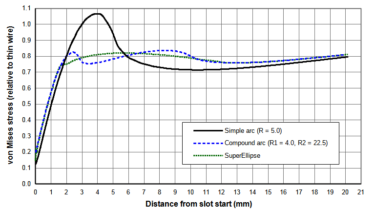
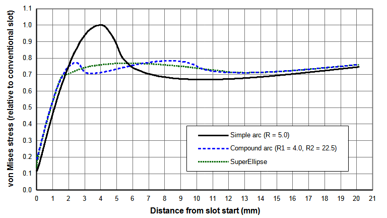
Slot comparisons
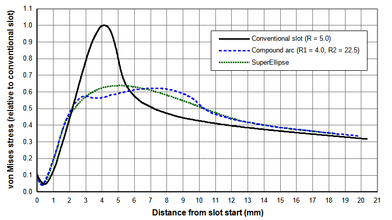
Figure N shows comparisons between the several slot configurations. The smooth stress contour of the superellipse seems aesthetically more pleasing than the compound arc. However, both give similar stress reductions compared to a conventional slot (22% for the compound arc design versus 23% for the superellipse design). The compound arc should be somewhat easier to program for CNC machining. However, both should machine equally since their contours are very similar.
|
||||||||||
|
Changes in resonant frequencies
When a standard slot is replaced by an optimized design, the resonant frequencies show minimal change. Also, the uniformities show minimal change. Table 3 shows this for the analyzed horn. Hence, an optimized design can be directly substituted for the conventional design.
|
||||||||||||||||||||||||
|
Note — \( f_1 \) is the lowest frequency within the specified frequency range (16 kHz – 24 kHz). It is not the lowest possible frequency for this horn. Similarly for \( f_n \) (the highest frequency within the specified frequency range).
Other geometries
Ciomber [1] presents several proposed geometries for reducing stress in an axially loaded bar (see p. 29). Simões [1] uses a gradientless optimization algorithm to improve the stress in fatigue test specimens. This is an iterative approach whereby the slot is modeled with a cubic spline and the spline's control points are individually adjusted to achieve the optimum condition — where the stress is too high the spline point is adjusted inward (i.e., remove material) and vice versa. Some of these techniques could be applied toward reducing ultrasonic stresses in slots. Waldman presents a superconic (generalization of superellipse, superparabola, and others) that could be tried. However, since the current optimized designs give reasonably constant slot stresses after exiting the \( R4 \) arc, it seems unlikely that these alternate geometries would give substantially better results within the current design constraints (particularly for machining).
Application to other horns
20 kHz 125 mm x 125 mm block horn
A 20 kHz 125 mm x 125 mm block horn was analyzed with the above slot designs. This horn had two slots on each face. Each slot intersected a transverse slot from an adjoining face. Figure N shows the slot stress results. The highest stress in the conventional intersected slot is 2.4 times greater than for the non-intersected slot in the test bar horn (compare figure N(a) to figure N(a)). The slot with the compound arc reduces this stress by 38% while the slot with the SuperEllipse reduces this stress by 36% (figure N(b)).