Appendix A: Comparison of 33 and 31 ceramic operation
The ceramics that are used in power transducers typically fall into two categories.
- 33 type. For the 33 type the direction of ceramic vibration is parallel to the electric field. The ceramics are usually thin disks and the transducer uses multiple disks (generally at least one pair but sometimes as many as three or four pair, depending on the power handling requirements). This is the most common type.
- 31 type. For the 31 type the direction of ceramic vibration is perpendicular to the electric field. A single tube-shaped ceramic is typically used. This type is generally used only in special circumstances.
33 mode — Advantages
In a matched PZT4 parallel mode transducer, the strain and stress are less at a given driving electric field, but the bandwidth is up by a factor of 2.6 and the power by a factor of 1.7 compared to a matched PZT4 later mode transducer. (Morgan Technical Publication TP-221, pp. 14 - 15)
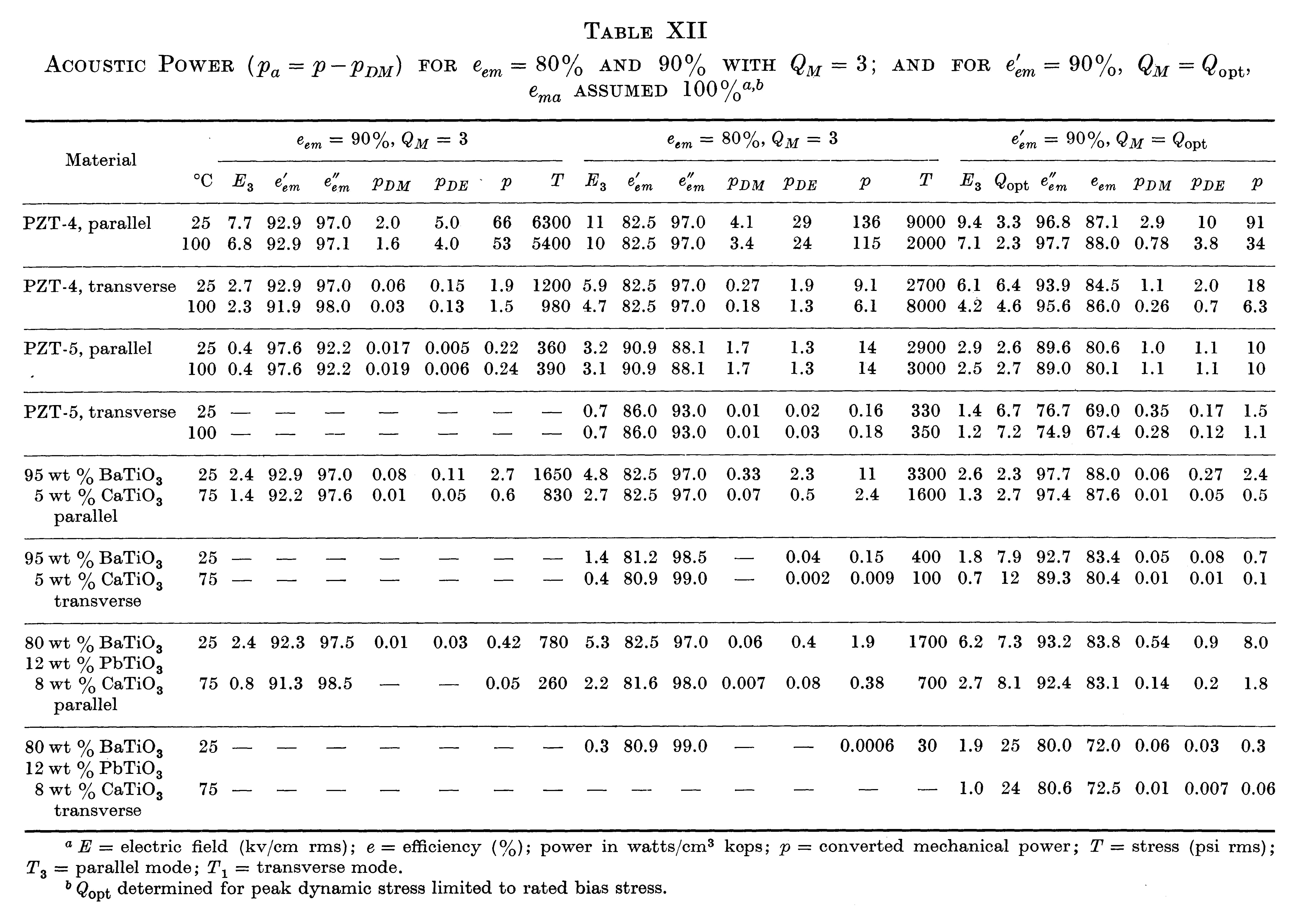
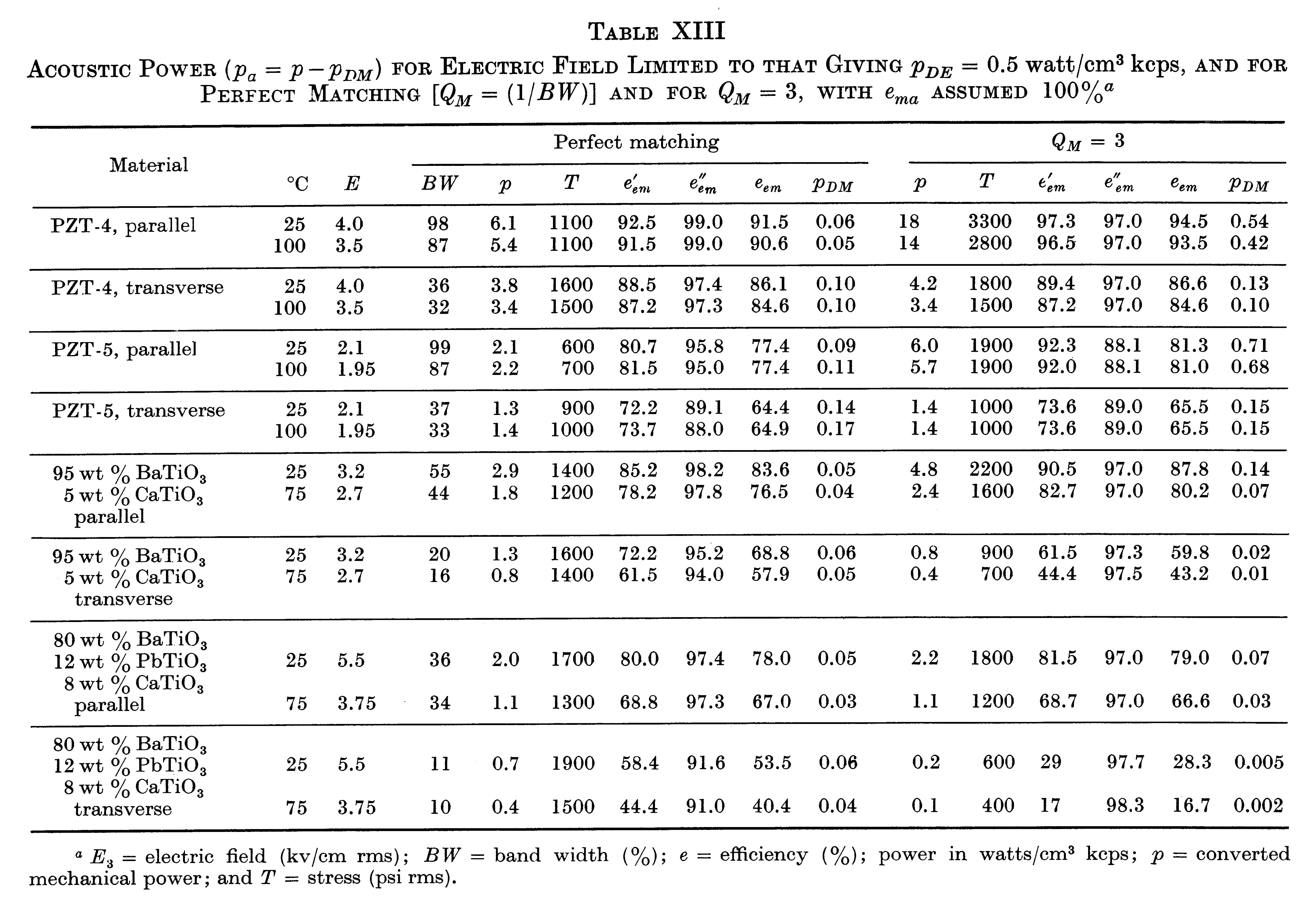
"The data in Tables XII and XIII show several advantages of the use of the parallel rather than the transverse mode in high power transducers. These include higher bandwidth, higher efficiency (\( e'_{em} \)) for the same power, and higher power for a given value of \( p_{DE} \) [electrical power dissipation]. Allowable bias stress is also higher in this mode." (Berlincourt (3), pp. 253, 255-256) Note particularly the PZT-4 data.
|
|
31 mode
The following are the advantages and disadvantages of using piezoelectric ceramics in the 31 mode. These may not all apply to a particular design or application.
Advantages
- Since the design may involve fewer parts (a single ceramic and one or two electrodes), the manufacturing costs may be less.
- Generally, a 31 design will have fewer ceramic interfaces so the mechanical loss from such interfaces is lower.
Disadvantages
- ".. approximately 5 times the ceramic is required to maintain the same output power level" compared to the 33 type. Channel Industries (1), p. 6
- The cost for electroding (inner and outer walls) is higher than for disks (33 type).
- The manufacturing cost may be higher because the yields for long cylinders may be lower than for disks (33 type).
- For a ceramic stack whose overall dimensions are identical, the frequency separation between series resonance (\( f_s \)) and parallel resonance (\( f_p \)) may be lower. Example: tube ceramic (0.650" OD x 0.300" ID x 1.000" long).
- The transducer may be difficult to mount at the node if ceramic tube spans the node.
zzz Insert table here
- For the 31 mode, figure A1(b) (Berlincourt (3), figure 16, p. 216) for PZT4 shows that there is a substantial decrease in \( d_{31} \)
with static compressive stress whereas \( d_{33} \) actually increases somewhat. Therefore, considerably lower compressive prestress can be tolerated in the 31 mode (Berlincourt (3), p. 249). This means that the dynamic ceramic strain, which is limited by the prestress, may be lower than desired and so the output amplitude may also be lower than desired.
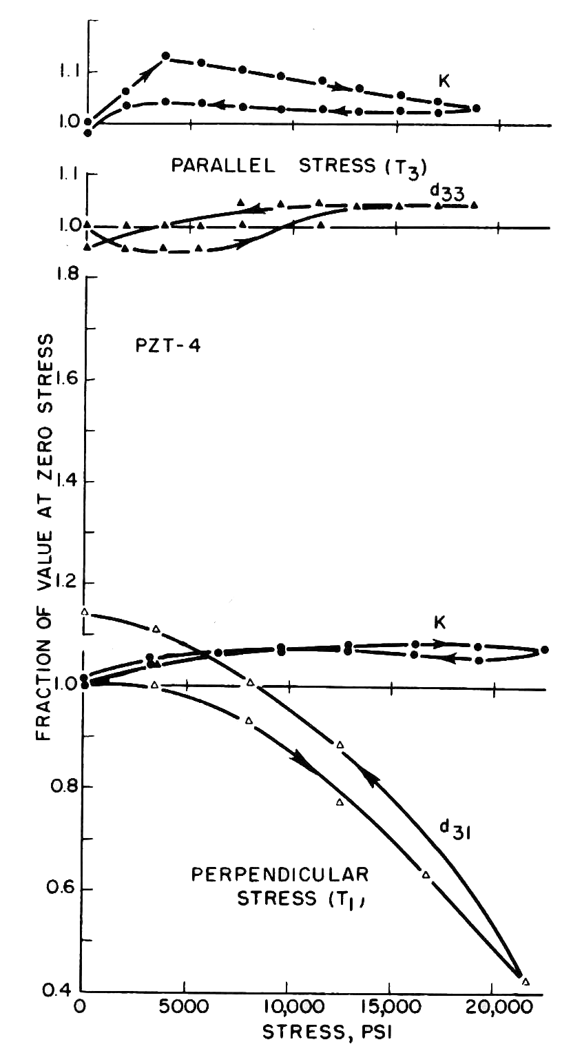
Figure A1. Effect of compressive stress -
(a) 33 direction (top two graphs), (b) 31 direction (bottom graph) - Figure A2 (Morgan Technical Ceramics (4), p. 6) for PZT4 shows that there is a substantial decrease in \( d_{31} \) over time as the static preload stress is maintained. In contrast, \( d_{33} \) actually increases somewhat. For instance, at 1000 hours \( d_{31} \)
has decreased about 29% while \( d_{33} \) has increased about 12%.
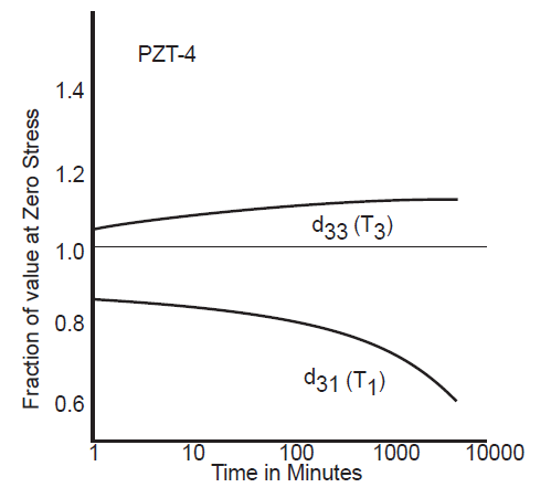
Figure A2. Aging of \( d_{33} \) and \( d_{31} \) with 10,000 psi [69 MPa] compressive stress
parallel (T3) and perpendicular (T1) to the poling axis
Recommendation
Except in special circumstances, the 33 mode should be used instead of the 31 mode.