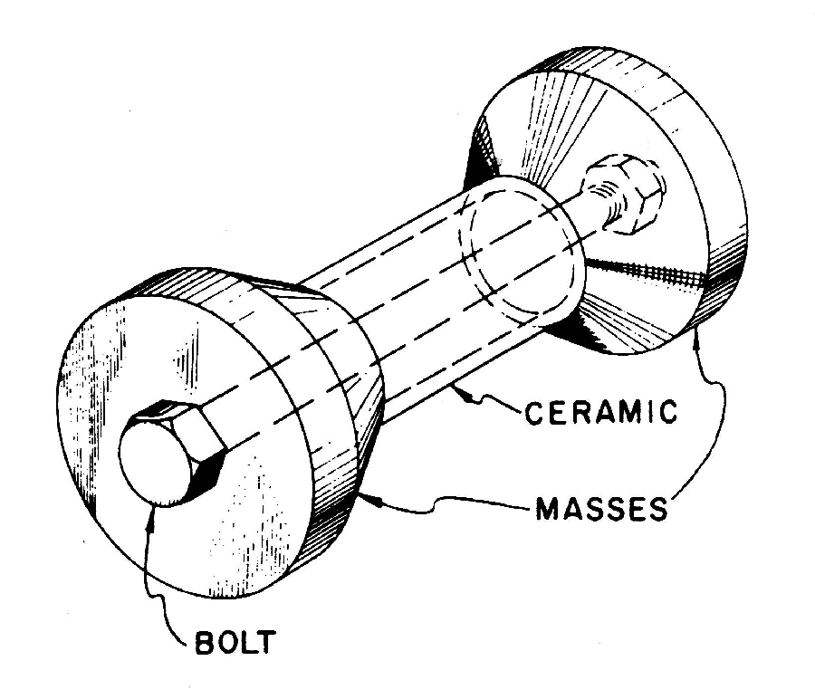
Appendix H — Effect of stack bolt on electromechanical coupling coefficient κ
When the ceramics are prestressed by a stack bolt, the electromechanical coupling coefficient \( kappa \) is reduced because the stiffness of the stack bolt reduces the normal expansion or contraction of the ceramics. This appendix derives the relationship. (Note: in this discussion, "stack bolt" refers to any means of applying a prestress to the ceramic stack. This could include a center stack bolt, peripheral stack bolts, or a peripheral shell.)
See Transducer design — stack bolt for a general discussion.
Consider a stack of \( n \) identical dielectric ceramics that are contained between two parallel rigid massless platens. When a D-C voltage \( V \) is applied to each ceramic, energy is transferred to the ceramics to charge the ceramic's capacitance. The total "capacitive energy" is —
\begin{align} \label{eq:10028a} \widehat{W}_c &= n \, \left( \small\frac{1}{2} \, C \, V^2 \right) \end{align}
where —
| \( \widehat{W}_c \) | = capacitive energy [coulomb-volt or joules] |
| \( C \) | = ceramic individual capacitance [coulomb/volt or farads] |
| \( V \) | = voltage [volts] |
| \( n \) | = number of ceramics |
If the ceramics also have piezoelectric properties then additional energy is transferred which causes the ceramic to expand or contract; this is the desired effect by which the applied electrical energy is transformed into mechanical (strain) energy. This strain energy is —
\begin{align} \label{eq:10027a} \widehat{W}_k &= \small\frac{1}{2} \, k \, U^2 \end{align}
where —
| \( \widehat{W}_k \) | = strain energy [N-m or joules] |
| \( k \) | = stiffness of ceramic stack [N/m] |
| \( U \) | = displacement of ceramic stack due to voltage \( V \) [m] |
If a stack bolt is present and is also connected between the two platens then the stiffness \( k \) includes the combined stiffness of the ceramics \( k_c \) and the stack bolt \( k_s \).
The electromechanical coupling coefficient \( \kappa \) (kappa) is given by Waanders (1), p. 12 as —
\begin{align} \label{eq:10026a} \kappa^2 &= {\left[\frac{\textsf{Energy converted}}{\textsf{Energy input}} \right]}_{\textsf {Low frequency}} \end{align}
Note the requirement of "low frequency" for which the measurement frequency is well below the resonant frequency of the device. Under this condition the inertial energy due to velocity is negligible compared to the strain energy due to deformation. Since \( \kappa \) is the ratio of two energies, \( \kappa \) must be dimensionless.
In the case where the ceramic stack is excited by an applied voltage, the "Energy converted" is the energy that is converted from electrical form to mechanical form. Hence, the numerator of equation \eqref{eq:10026a} is just the strain energy \( \widehat{W}_k \) of equation \eqref{eq:10027a}. The denomintor is the total input (system) energy (i.e., the combined energy of \( \widehat{W}_c \) and \( \widehat{W}_k \)). Thus, equation \eqref{eq:10026a} can be written as —
\begin{align} \label{eq:10029a} \kappa^2 &=\cfrac{\widehat{W}_k}{\widehat{W}_c + \widehat{W}_k} \\[0.7em]%complex_eqn_interline_spacing &= \cfrac{1}{\left( \cfrac{\widehat{W}_c}{\widehat{W}_k} \right) +1} \nonumber \\[0.7em]%complex_eqn_interline_spacing &= \cfrac{1}{\left( \cfrac{n \, C}{k} \right) {\left( \cfrac{V}{U} \right)}^2 +1} \nonumber \end{align}
Equation \eqref{eq:10029a} is perfectly general. It will be applied below when there is no stack bolt (case 1) and when a stack bolt is present (case 2).
Case 1 — no stack bolt
Assigning subscript 1 in equation \eqref{eq:10029a} to indicate that no stack bolt is present —
\begin{align} \label{eq:10030a} {\kappa_1}^2 &= \frac{1}{{\left(\Large\frac{n \, C}{k_1}\right) } \left(\Large\frac{V}{U_1} \right)^2 +1} \end{align}
Here \( k_1 \) is the stiffness of ceramic stack alone since there is no stack bolt. For convenience we designate this as \( k_c \).
Solving for \( \left(\frac{V}{U_1}\right)^2 \) (for later use) —
\begin{align} \label{eq:10031a} \left(\frac{V}{U_1} \right)^2= \frac{\Large{\frac{1}{{\kappa_1}^2}} -1}{\left(\Large\frac{n \, C}{k_c}\right) } \end{align}
Dependence of \( \kappa \) on test parameters
It might appear that \( \kappa \) given in equation \eqref{eq:10030a} depends on the particular test parameters (e.g., \( C \) and \( k_c \) which both depend on the ceramic dimensions, and also \( n \), \( V \) and \( U \)). In fact, however, \( \kappa \) depends only on the electromechanical properties of the ceramic, as demonstrated below.
Consider how the parameters in equation \eqref{eq:10030a} are related to the ceramic dimensions (resulting in equations \eqref{eq:10031b}, \eqref{eq:10031c}, and \eqref{eq:10031d} below).
Consider \( C \) —
\begin{align} \label{eq:10031b} C &= {\frac{\varepsilon \, A_c}{h_c}} \end{align}
where —
| \( \varepsilon \) | = ceramic permittivity [(coulomb/volt)/m] |
| \( A_c \) | = cross-sectional area of ceramic (i.e., the area of the individual ceramic's flat face) [m²] |
| \( h_c \) | = height (thickness) of each ceramic [m] |
Consider \( k_c \) —
\begin{align} \label{eq:10031c} k_c &= {\left( \frac{1}{n} \right) \left( \frac{Y_c \, A_c}{h_c}\right)} \end{align}
where —
| \( Y_c \) | = Young's modulus of the ceramic |
Consider \( \frac{V}{U_1} \) —
\begin{align} \label{eq:10031d} \frac{V}{U_1} &= \frac{V / h_c}{U_1 / h_c} \\[0.7em]%complex_eqn_interline_spacing &= \frac{V / h_c}{n \, \left[ \left(U_1/n \right) / h_c \right]} \nonumber \\[0.7em]%complex_eqn_interline_spacing &= \frac{E}{n \, \epsilon} \nonumber \\[0.7em]%complex_eqn_interline_spacing &= \frac{1}{n \, (\epsilon / E)} \nonumber \\[0.7em]%complex_eqn_interline_spacing &= \frac{1}{n \, d_{33}} \nonumber \end{align}
where —
| \( E \) | = electric field strength [v/m] |
| \( \epsilon \) | = strain in each ceramic [v/m] |
| \( d_{33} \) | = piezoelectric strain constant [m/v] or charge constant [Coulonb/N] |
In equation \eqref{eq:10031d}, note that \( U_1 \) is the combined desplacement of all of the ceramics (i.e., the entire ceramic stack). Therefore, \( U_1/n \) is the displacement of a single ceramic so \( (U_1/n)/h_c \) is the strain \( \epsilon \) in a single ceramic. Then that strain \( \epsilon \) divided by the electric field strength \( E \) is just the piezoelectric strain constant \( d_{33} \).
Now, substituting equations \eqref{eq:10031b}, \eqref{eq:10031c}, and \eqref{eq:10031d} into \eqref{eq:10030a} gives —
\begin{align} \label{eq:10031e} {\kappa_1}^2 &= \frac{1}{{\left(\Large\frac{\varepsilon}{Y}\right) } \left(\Large\frac{1}{d_{33}} \right)^2 +1} \end{align}
Thus, when no bolt is present the electromagnetic coupling \( \kappa_1 \) depends only on properties of the ceramic, not on the number of ceramics or other parameters of the test. It should be noted, however, that some of the ceramic "properties" depend on the electrical and mechanical boundary conditions.
As discussed above, the electromechanical coupling factor \( \kappa \) is the ratio of energies and so should be dimensionless. Thus, the right side of \eqref{eq:10031e} should also be dimensionless. Performing a dimensional analysis on the variables in the denominator of \eqref{eq:10031e} gives —
\begin{align} \label{eq:10031f} \left( \frac {\left( \frac{coulomb/volt}{m} \right)} {\left( \frac{N}{m^2} \right)} \right) \left(\frac{1}{volt/m} \right)^2 = \frac{coulomb \, volt}{N \, m} = \frac{joule}{joule} = dimensionless \end{align}
Case 2 — with stack bolt
Assigning subscript 2 in equation \eqref{eq:10029a} to indicate that a stack bolt is present —
\begin{align} \label{eq:10032a} {\kappa_2}^2 &= \frac{1}{{\left(\Large\frac{C}{k_2}\right) } \left(\Large\frac{V}{U_2} \right)^2 +1} \\[0.7em]%complex_eqn_interline_spacing &= \frac{1}{{\left(\Large\frac{C}{k_2}\right) } \left(\Large\frac{V}{U_1} \right)^2 \left(\Large\frac{U_1}{U_2} \right)^2 +1} \nonumber \end{align}
\( k_2 \) is the total stack stiffness. Since the ceramics and bolt are mechanically in parallel, the \( k_2 \) just equals the ceramic stiffness plus the bolt stiffness —
\begin{align} \label{eq:10032b} k_2 = k_c + k_b \end{align}
where —
| \( k_2 \) | = total stack stiffness [N/m] |
| \( k_c \) | = total ceramic stiffness [N/m] |
| \( k_b \) | = bolt axial stiffness [N/m] |
Thus equation \eqref{eq:10032a} becomes —
\begin{align} \label{eq:10032c} {\kappa_2}^2 &= \frac{1}{{\left(\Large\frac{C}{k_c \, + \, k_b}\right) } \left(\Large\frac{V}{U_1} \right)^2 \left(\Large\frac{U_1}{U_2} \right)^2 +1} \end{align}
For a given ceramic configuration the stack displacement \( U \) varies inversely with the stack stiffness. Thus, generally —
\begin{align} \label{eq:10033a} U \,\propto \, \frac{1}{k} \end{align}
Then the relative displacements \( U_1 \) without a stack bolt and \( U_2 \) with a stack bolt can be expressed in terms of the stiffnesses as —
\begin{align} \label{eq:10034a} \frac{U_1}{U_2} &= \frac{k_2}{k_1} \\[0.7em]%complex_eqn_interline_spacing &= \frac{k_c \, + \, k_b}{k_c} \nonumber \\[0.7em]%complex_eqn_interline_spacing &= \frac{k_b}{k_c} + 1 \nonumber \end{align}
Substituting equations \eqref{eq:10031a} and \eqref{eq:10034a} into equation \eqref{eq:10032c} and simplifying gives —
\begin{align} \label{eq:10037a} {\kappa_2}^2 &= \frac{1}{ \left({\Large\frac{1}{{\kappa_1}^2}} -1 \right) \left({\Large\frac{k_b}{k_c}} +1\right) +1} \end{align}
where (finally) —
| \( \kappa_2 \) | = piezoelectric coupling coefficient with the stack bolt |
| \( \kappa_1 \) | = piezoelectric coupling coefficient without the stack bolt |
Berlincourt[3] (p. 269, endnote 9, referenced on p. 249) gives the same equation for a heavily mass-loaded transducer, although with slightly different notation and some rearranging. (An ideal heavily mass-loaded transducer is one with centered ceramics whose ceramic volume is small compared to the two end masses which are assumed to be infinitely rigid (i.e., no strain). Then when the transducer vibrates at resonance, the ceramics and stack bolt experience nearly uniform strain. Such uniform strain is the same as was assumed here for static loading.)
|
|
|
If there is no bolt (so \( k_b = 0 \)) then \( \kappa_2 = \kappa_1 \), as expected. As the bolt stiffness \( k_b \) increases, \( \kappa_2 \) is progressively reduced below \( \kappa_1 \). If the bolt stiffness \( k_b \) becomes (theoretically) infinite then \( \kappa_2 \) is zero. This is because the stack is restrained by the bolt against any expansion regardless of the applied voltage. Thus, all of the applied voltage goes toward charging the ceramic and none causes expansion of the ceramic.
For each component of the ceramic stack, the stiffnesses can be expressed in terms of the component's modulus and dimensions —
\begin{align} \label{eq:10038a} k &= Y A / h \end{align}
where —
| \( Y \) | = Young's modulus |
| \( A \) | = cross-sectional area |
| \( h \) | = height (length) of component |
Thus, in terms of the actual ceramic and bolt parameters, equation \eqref{eq:10037a} can be written as —
\begin{align} \label{eq:10039a} {\kappa_2}^2 &= \frac{1}{ \left({\Large\frac{1}{{\kappa_1}^2}} -1 \right) \left({\Large\frac{Y_b \, A_b \, / \, h_b}{Y_c \, A_c \,/ \, (n \, h_c)}} +1\right) +1} \end{align}
where —
| \( Y_b \) | = Young's modulus of bolt |
| \( A_b \) | = cross-sectional area of bolt shank |
| \( h_b \) | = length of bolt |
| \( Y_c \) | = Young's modulus of ceramic |
| \( A_c \) | = cross-sectional area of ceramic (i.e., the area of the individual ceramic's flat face) |
| \( h_c \) | = height (thickness) of individual ceramic |
| \( n \) | = number of ceramics |
Note that \( n \, h_c \) is just the total ceramic stack height. Also note that \( h_b \) could be longer than \( n \, h_c \) without violating the requirements of the above derivations.