Uniformity — methods for improving
(preliminary)
Contents
- Figures
- Figure 1. Cylindrical horn with peripheral groove
- Figure 20. Bar horn with splayed slots (Holze)
- Figure 25. Bar horn with risers (Holze)
- Figure 27. Bar horn (4 slots) with side risers
- Figure 30. Bar horn (2 slots) with transverse holes (Scotto)
- Figure 32. Bar horn (4 slots) with transverse holes (Scotto)
- Figure 40. Bar horn with unequal shoulder lengths (Harris)
- Figure 50. Bar horn with additional half-wave resonators on the input surface (Elbert)
- Figure 60. Bar horn with additional half-wave resonators on the input surface (Scotto)
There are two basic methods for improving face amplitude uniformity — by increasing the amplitude of low amplitude regions and/or decreasing the amplitude of high amplitude regions.
Need for adjustability
FEA is often used to optimize a horn's uniformity. For simplicity, FEA generally assumes that the material is isotropic. However, aluminum is somewhat orthotropic and titanium is moderately orthotropic. Thus, the uniformity of the machined horn will often be different than that predicted by FEA.
In addition, FEA assumes that the material properties remain consistent. However, the properties of titanium are known to vary from lot-to-lot and even within the same piece of material (nonhomogeneous).
Hence, a method for controlling the uniformity should preferably allow for some final adjustments after the horn has been machined.
Remove material behind low-amplitude regions
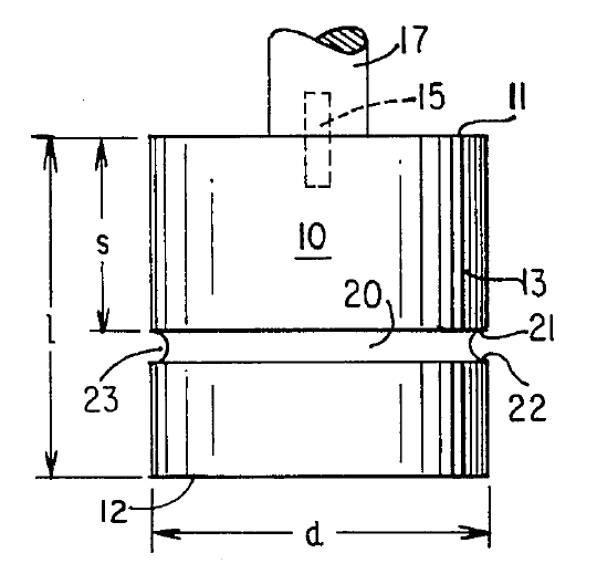
Material may be removed behind a low-amplitude region (e.g., by undercutting) such that a flange is created. Since the flange material is no longer well supported, it can "flap" due to its inertia. This flapping increases the amplitude in the region of the flange relative to higher-amplitude regions. The effect is somewhat localized near the removed material. This method can be primary (as with spool horns) or secondary (as with flanges added to the ends of bar horns)..
Figure 1 shows this method where a peripheral groove has been machined into a cylindrical horn in order to increase the amplitude at the periphery of the horn's face (Davis[2] patent 4131505). The groove's position and dimensions affect the amplitude distribution across the horn's face (figure 2).
Redistribute the gain
Figure 20 shows a patent by Holze that uses splayed slots to redistribute the gain in a bar horn. By angling the slots outward, the end elements have greater mass behind the node and reduced mass in front of the node, thereby increasing the gain of these elements. Conversely, the center element has reduced mass behind the node and increased mass in front of the node, thereby reducing the gain of the center element. The net effect is that the outboard face amplitude increases while the central face amplitude decreases. If the slot angles are correctly chosen then the outboard amplitude will nearly equal the central amplitude — i.e., the uniformity will be substantially improved compared to a bar horn with non-splayed slots. (Typically the optimum slot angles are less than 10° with respect to the stud axis.)
Unfortunately, this design doesn't allow for much adjustment after machining since the relative element amplitudes are determined by the fixed slot angles. Hence, this design is not widely used.
Reduce the frequency of low-amplitude elements
Using a spring mass analogy for a 2-slotted bar horn, Culp has shown that the amplitudes of low-amplitude elements can be increased by reducing their frequencies relative to elements with higher amplitudes. Scotto also recognized this effect.
This applies mainly to slotted bar horns and somewhat to slotted block horns. The frequency of low-amplitude elements can be reduced by adding risers (figure 25), adjusting the nodal radii (figure 40), adding nodal holes (figures 30 and 32), or contouring the slots. Secondarily, the uniformity of slotted horns will be affected by the slot parameters: lateral locations, widths, and web lengths.
These methods are advantageous because they allow adjustment of the uniformity after the horn has been machined. The general method is to select the elements that have low amplitude and gradually reducing their frequencies until the optimum uniformity has been achieved. Of course, as the frequencies of these elements are reduced, the horn's overall frequency will also be reduced so retuning during this process would be needed.
Risers
Additional mass can be selectively added to a horn's input surface to reduce the frequencies of the associated elements. These masses are here called "risers" but have also been called "castellations" or "end/rear/back masses". (The latter terms are not preferred since they are also used for the rear-most elements of transducers.)
This method was patented by Holze; figure 25 shows the risers (entities 36). The Holze patent indicated that the increased amplitude of the riser elements could be attributed to their increased gain (due to the additional rear mass). However, this assumption is incorrect since the riser concept also works for unshaped horns which inherently do not have gain.
For adjustment the risers are initially made too long for which the element frequencies will be lower than desired and the associated element amplitudes will be too high. Then the element lengths are gradually reduced (thereby increasing their frequencies and reducing their amplitudes) until the optimum face amplitude is achieved. (Note that the overall output amplitude will increase because the increased amplitude of the riser elements will also indirectly increase the amplitude of the adjacent non-riser elements through the tug of the slot webs.)
(The risers are most effective when they exactly cover the associated element without extending into the slot area.)
Risers are easily used with multi-slotted block horns because they can be positioned over any of the horn's elements. However, the effect on amplitude is generally largest for the peripheral elements.
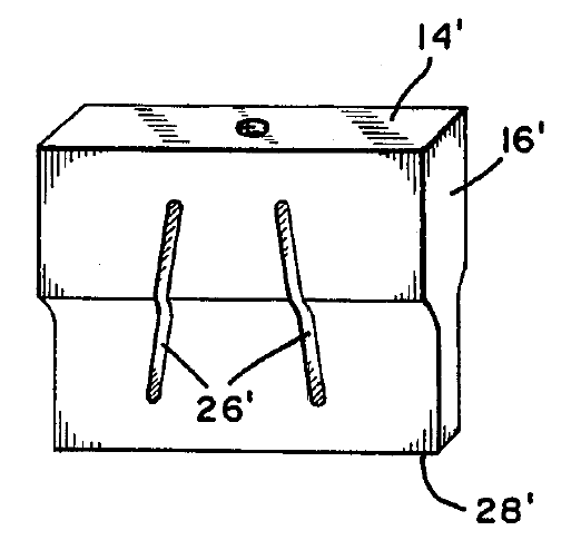
One disadvantage of this design is that the back risers may interfere with the supporting equipment (either the stand or the booster). This can be handled by adding the risers to the sides of the horn rather than at the back (figure 27). The effects on element frequencies and amplitudes are the same. However, this requires thicker initial horn material (higher material cost plus increased machining cost). On multislotted block horns the side risers can only be applied to peripheral elements so only the amplitudes of these peripheral elements will be affected.
|
|
| Figure 27. Bar horn (4 slots) with side risers |
|
Lateral nodal holes
Lateral holes near a node can be used to decrease the frequencies of the associated elements (e.g., figures 30 and 32). For the horns of these figures, the hole diameters can initially be machined undersized and then increased until the desired uniformity has been achieved. For the designs of these figures, the holes are located in areas of relatively low stress because of the gain of these shaped horns. However, if these holes are used in unshaped horns then the relative stress (for a given output amplitude) is significantly higher. For multi-slotted block horns the holes can be used to adjust the amplitudes of outer elements. (Culp designed such a titanium horn but it ultimately failed at the nodal hole.)
Unequal shoulder lengths
The horn is initially designed or machined with equal shoulder lengths (entities 20 and 22 in figure 40). The nodal radii (24) are then machined back (reducing the shoulder lengths 20) until the desired uniformity has been achieved. The disadvantage of this design is that the nodal radii of the end elements are somewhat difficult to machine. This is especially true of wide bar horns that have more than two slots.
As discussed, the general principle here is to reduce the frequency of the low-amplitude elements (in this case, the end elements) to that their amplitude increases relative to the high amplitude center element. The same principle can be applied to cross-slotted block horns by banding the elements that have low amplitude. However, such banding can typically only be done on external surfaces (sides or ends) so the banded element is no longer geometrically symmetric.
Other methods
Other methods have been proposed but do not seem to have been widely used because of limitations.
Add additional half-wave resonators on the horn's input surface
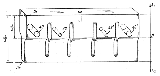
Figure 50 shows a patent by Elbert where cylindrical half-wave resonators (16a and 16b) are attached to the input surface of the two-slotted bar horn. (Entity 14 is the transducer and entities 80a are nodal grooves by which the assembly can be supported.) Elbert doesn't speculate on the reason why the cylindrical resonators improve the face uniformity of the horn. However, it seems likely that they are detuned to a somewhat lower frequency so their effect is similar to the risers that were discussed above. In addition, these cylindrical resonators may have some lateral flexural motion that counteracts the low amplitude of the horn's end elements. If so, then the diameters of these cylindrical resonators may be an important design parameter since these diameters affect the amount of flexure motion.
Elbert's patent (1986) seems to be very similar to Scotto's[1] 1974 French patent (2203295). The details of Scotto's patent could not be found. However, figure 60 shows an image from Derks[1] (p. 31).
Add keyhole slots
Cardoni [1] found that adding narrow (keyhole) slots between the conventional slots could considerably improve the uniformity of block horns. However, the consequential increase in slot stress (and possible reduction in horn life) was not considered.
Block horns
Block horns have slots in both the thickness and width directions. Some of the above methods can also be applied to block horns.
![Figure 25. Bar horn risers (Holze[3] patent 4363992)](_images/holze_patent_4363992__fig4__10b.png)
![Figure 40. Bar horn with unequal shoulder lengths (Harris[1] patent 4651043)](_images/harris_patent_4651043__fig1__10d.png)
![Figure 50. Bar horn with additional half-wave resonators on the input surface (Elbert[1] patent 4607185)](_images/elbert_patent_4607185__fig1__10c.png)
![Figure 60. Bar horn with additional half-wave resonators on the input surface (Scotto[1] patent 2203295)](_images/scotto_patent_2203295__10b.png)