\( Q \) (quality factor)
Contents
- Overview
- Interpretation
- \( Q \) for resonator materials
- Incorrect interpretation
- \( Q \) measurement
- Also see
- Figures
- Tables
- Table 1. \( Q \) for various materials
Overview
\( Q \) (quality factor) is a property that relates the total stored energy to the energy dissipated (loss) —
\begin{align} \label{eq:13601a} Q = 2\pi \left[ \frac{\textsf{Energy stored}}{\textsf{Energy dissipated per cycle}} \right] \end{align}
The "energy dissipated per cycle" is the external energy (work) that would be needed in order to maintain a fixed amount of oscillation.
If the numerator and denominator are multiplied by the frequency \( f \) (cycles/sec), the denominator becomes "Energy dissipated/sec" (i.e., Power), so the above equation can also be written as —
\begin{align} \label{eq:13602a} Q = 2\pi \, f \left[ \frac{\textsf{Energy stored}}{\textsf{Power}} \right] \end{align}
\( Q \) has no units.
\( Q \) can be determined for any system (electrical, mechanical, etc.) or any single component or portion of a system. Note that for a "perfect" system (i.e., no energy dissipation), \( Q \) is infinite.
Interpretation
Resonant system
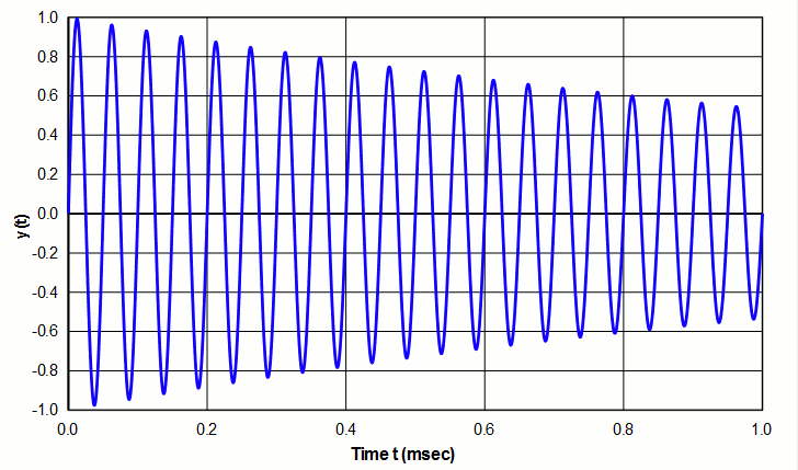
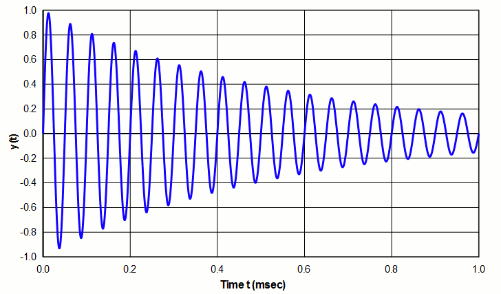
For a freely oscillating resonant system, \( Q \) indicates the rate at which oscillation decays due to energy loss. A high \( Q \) indicates relatively slow decay (example of figure 1) whereas a low \( Q \) indicates relatively rapid decay (example of figure 2 - see log decrement ).
|
|
|
|
|
|
In an ultrasonic system the energy loss may come from internal friction within a vibrating material (which will show up as a temperature rise), energy that is transferred to the support structure or air, or energy that is transferred to the load. In addition, a transducer will have electrical (resistive) losses due to current flow.
Nonresonant system
Although Q is often applied to resonant systems, this is not a requirement. In fact, equations \eqref{eq:13601a} and \eqref{eq:13602a} can equally be applied to nonresonant systems — in particular, to capacitors and inductors.
A nonideal capacitor (i.e., a capacitor with loss) can be represented as an ideal capacitor \( C \) in series with a resistor \( R_C \).
For a capacitor —
\begin{align} \label{eq:13603a} Q &= \frac{R_C}{(1/2\pi \, f \, C)} \\[0.7em]%eqn_interline_spacing &= R \, (2\pi \, f \, C) \nonumber \end{align}
For an inductor —
\begin{align} \label{eq:13604a} Q &= \frac{R_L}{(2\pi \, f \, L)} \end{align}
where —
| \( R_C \) | = equivalent resistance of capacitor |
| \( R_L \) | = equivalent resistance of inductor |
| \( C \) | = capacitance |
| \( L \) | = inductance |
| \( f \) | = frequency |
Incorrect interpretation
If a material's \( Q \) is known then from equation \eqref{eq:13602a} —
If a material's \( Q \) is known and if the stored energy (either potential energy (i.e., strain energy) or kinetic energy) can be determined or calculated, then the theoretical power dissipated by a resonator can be calculated from equation \eqref{eq:13602a} —
\begin{align} \label{eq:13605a} \textsf{Power} = 2\pi \, f \left[ \frac{\textsf{Energy stored}}{Q} \right] \end{align}
Note that although \( Q \) is related to power loss, it is not the actual power loss since \( Q \) also depends on energy storage. For example, consider two identical horns, one made of titanium and one made of heat treated steel. Assume that both materials have the same \( Q \); then both identical horns will also have the same \( Q \). (This can actually be realized with the correct conditions.) It might be tempting to say that because both horns have the same \( Q \), they therefore will have the same loss. However, steel has 1.5x greater density and 1.5x greater modulus than titanium. Thus, its stored energy will be 1.5x greater than titanium for which equation \eqref{eq:13605a} shows that its loss will also be 1.5 times greater.
Q dependence on frequency
For resonator materials the relationship between \( Q \) and frequency is not precisely established. In Mason's tests of Ti-6Al-4V, he found that Q was independent of frequency up to XXX MHz (figure X). On the other hand, ZZZ found that \( Q \) for aluminum decreased somewhat with frequency (figure Y). However, it may be reasonable to assume that \( Q \) is reasonably constant over a limited frequency range.
Q dependence on test conditions
\( Q \) may depend on the following test conditions —
Loading mode
Just as a material may be characterized by two elastic moduli (modulus of elasticity and modulus of rigidity) which depend on how the material is loaded, \( Q \) may also depend on the loading mode. Thus, when evaluating test data for \( Q \), it may be necessary to determine if the tests were tensile (most likely) or shear. For situations where the material is loaded axially or in bending, the elements undergo a volumetric change. On the other hand, under shear loading (e.g., torsional) the elements don't experience a volumetric change. (Fine[1A] p. 60) Thus, it would be reasonable to question whether the mode of dissipation and degree of dissipation would be the same in these cases.
As Bedford[1A] p. 2 notes —
The mechanism of dissipation is not well understood, but it is probably correct to say that \( Q \) depends not only upon the material, but also upon the geometrical configuration and mode of vibration. \( Q \) is defined as the ratio or energy stored to energy dissipated per cycle. Stored energy certainly depends upon configuration and mode through the equivalent mass and compliance parameters. It seems unlikely that dissipated energy would vary in such a way as to maintain \( Q \) constant when mode and configuration are changed.
Zemanek[1C] (p. 1285) commented that flexural resonances are more highly damped than longitudinal resonances. However, it is not clear if he meant this as an inherent characteristic of the flexural mode or whether this was due to his means of exciting the flexural mode.
The material's heat treatment
When tool steels are hardened they typically have significantly lower loss (power) and, hence, higher \( Q \). On the other hand, when Ti-6Al-4V is heat treated to the STA condition, its \( Q \) decreases.
Strain level
Often \( Q \) decreases as the strain increases but this depends on the particular material. This is particularly true for piezoceramics.
eonfwoeidsl
Operating conditions
For piezoelectric cermics \( Q \) depends on the operating conditions (static compression, electrical field, temperature, strain, etc.).
Q for resonator materials
|
|||||||||||||||||||||||||||||||||||||||||||||||||||||||||||||||||||||||||||
|
Notes —
- Wuchinich[1] (figure 10) measured these values by striking a flexing "chime". However, because the strains were low, the cited values may not be relevant at strains that are typical of ultrasonic devices.
- Neppiras[1A] (table 4, p. 146).
\( Q \) measurement
For a resonant system \( Q \) can be determined by the following methods. To obtain a correct measurement, \( Q \) must be measured under the actual operating conditions of the system (above).
Also see —
Attenuation
Damping ratio
Loss tangent
Structural damping

