Power supplies
Contents
- Figures
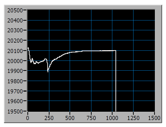
- Figure 0. Stack frequency during ultrasonic metal welding
- Figure 1. 20 kHz industrial transducer with six piezoelectric ceramics (33 mode)
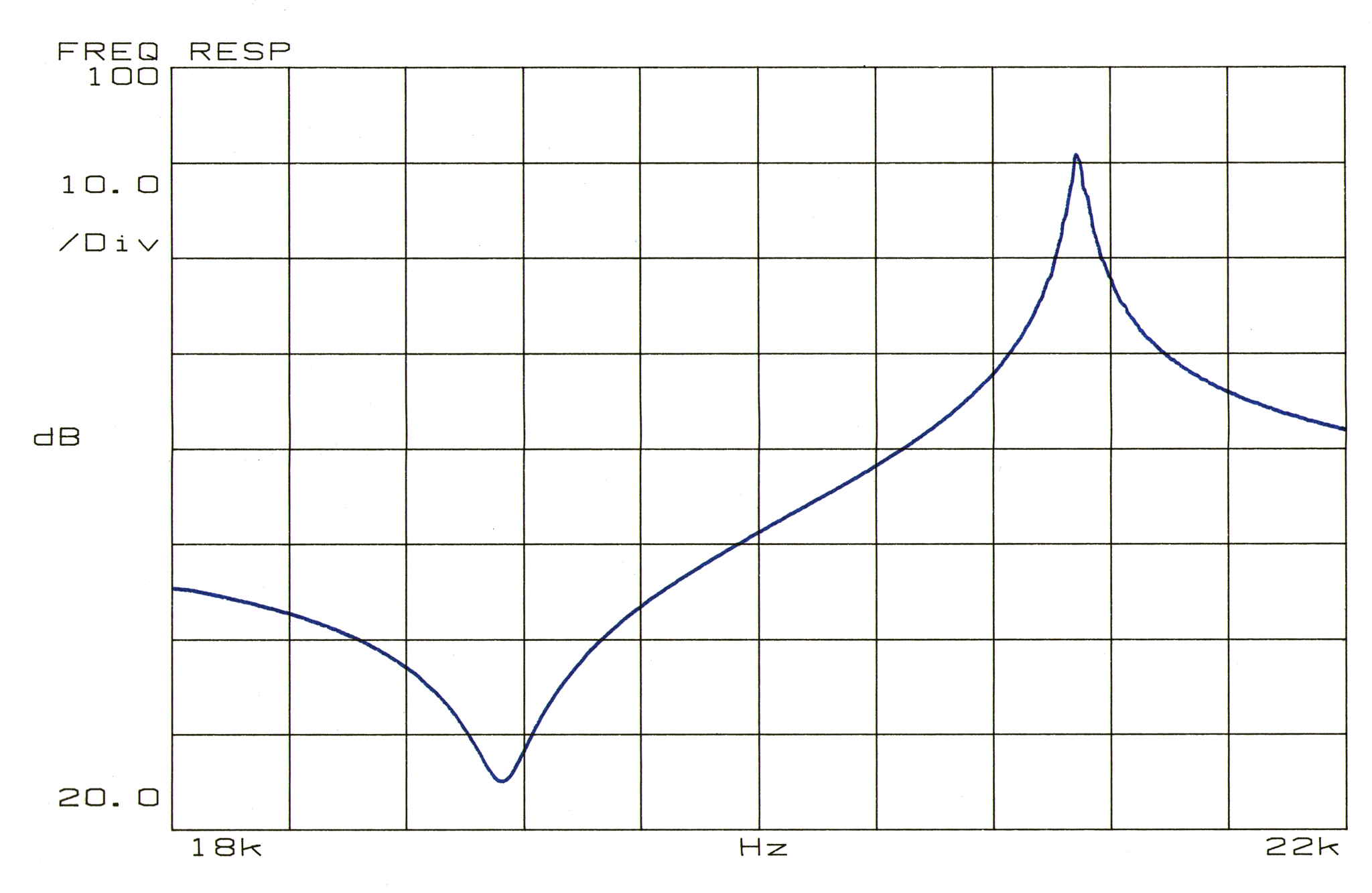
- Figure 2. Frequency response impedance plot for a 20 kHz transducer
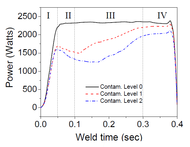
- Figure 3. Effect of surface contamination on weld power
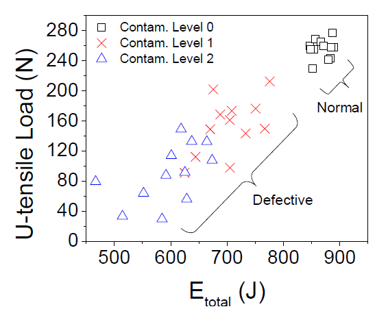
- Figure 4. Effect of energy input on weld strength
A power supply is an electrical device that converts standard 50 Hz or 60 Hz input voltage into high frequency output voltage that is suitable for driving an ultrasonic transducer. The magnitude and waveform of the output voltage is adjusted to meet the ultrasonic requirements.
Note — This topic discusses the general power supply requirements but not the specifics of the circuitry (except for the requirements of a tuning inductor).
Power supply sophistication
The instantaneour power characteristics of an application fall into four categories (generally depending on the type of load) which, in part, determine the required sophistication of the power supply —
- Constant power. The power is constant for the duration of the load cycle. This occurs when the load is relatively constant such as in atomizing or cavitation.
- Variable but predictable power. The power varies throughout the load cycle but in a predictable manner — i.e., the power variation is the same from one load cycle to the next. Ultrasonic inserting is an example.
- Variable but semi-predictable power. The power varies throughout the load cycle but in a semi-predictable manner — i.e., the general power trend is the same but there may be some variation from part-to-part. For example, some metal welding parts may have thicker oxide or plating layers that require more time to scrub through. Similarly, some plastic welding parts may have more mold release.
- Unpredictable power. The power can be predicted over a large range but instantaneous power can't be predicted. An example is ultrasonic bone cutting where the composition of the bone varies with the cut depth and where the application by the surgeon vaires (e.g., variation in applied force, twisting or bending of the blade, amount of lubrication, etc.).
Resonance type
The power supply must be specified to operate at either series or parallel resonance. (In certain circumstance an intermediate frequency may be specified.) Each of these resonances may have certain advantages but both are widely used in practice. Whichever is chosen, the transducer must be compatible (i.e., a transducer that is designed for series resonance will not operate properly at parallel resonance and vice versa).
Primary requirements
In certain situations a wide band power amplifier might be suitable for driving the ultrasonic stack. However, most dedicated ultrasonic power supplies have certain specialized circuitry/software that allows improved performance.
Auto-tuning
Lock onto the primary resonance
All ultrasonic systems have a primary resonance (the desired operating resonance). In addition there will be secondary (spurious) resonances. When the power supply starts, it must lock onto the primary resonance and ignore the secondary resonances.
Track the primary resonance
During ultrasonic operation the frequency of the primary resonance may shift.
- The frequency may drift lower as the stack temperature increases (either due to internal losses or from heat that is transferred from the load).
- The frequency may drop under heavy power because of nonlinearity of the ceramics.
- The frequency may shift because of reaction to the load. The shift may be either positive or negative. For example, figure 0 shows a frequency drop of approximately 200 Hz during ultrasonic metal welding (Vlad[1]).
|
|
|
Regardless of the cause, the power supply must be able to automatically follow this frequency shift. Otherwise, a small shift in frequency would cause a significant collapse in the stack output amplitude. This is because ultrasonic stacks typically have a very narrow bandwidth. For example, for the 20 kHz industrial transducer shown in figure 1, Culp[0] determined an open-circuit bandwidth of ~40 Hz (i.e., a Q of ~500) from measurements of amplitude decay when the drive source was suddenly disconnected. In this case a frequency shift of just 20 Hz from resonance would reduce the transducer's amplitude by 30% and available power output by 50% (assuming constant electrical input).
When additional stack components (booster + horn) are added, the situation becomes even worse (the Q increases and the bandwidth decreases). Then frequency tracking becomes even more critical. Note, however, that under load the Q may decrease significantly (i.e., the bandwidth increases) as energy is delivered to the load.
Frequency tracking is often handled by a phase lock loop (PLL) where the phase angle between the current and voltage is maintained at a constant value. Ideally the current and voltage would be exactly in phase so that the load would appear to be entirely resistive (i.e., no reactive component). However, in practice this may not be possible in high-Q (narrow bandwidth) system where a small change in frequency results in a large change in phase. In such a system the PLL may have difficulty maintaining the phase. In this case a slightly out-of-phase operation can allow better performance of the PLL.
|
|
|
|
|
|
Auto-adjust amplitude
Most applications can be best controlled by controlling the output amplitude rather than the power. The reason is that the power is the product of force and velocity (where the velocity is related to the output amplitude). Thus, a given power can be achieved by a high force with low velocity or a low force with high velocity or something inbetween. Although all of these conditions can yield the same power, the application may respond best to only one of these. Hence, amplitude should be regarded as the independent (input controlled) variable and power should generally be regarded as the dependent (output resultant) variable.
When the stack runs in air (i.e., unloaded) it will have a given output amplitude. This is the specification. Under load, however, the amplitude tends to collapse. At higher loads the amplitude collapse would be greater. This is analagous to a car that is being driven with a fixed throttle position. The car's speed is reduced on hills — the steeper the hill the greater the speed reduction.
The power supply needs some method of monitoring the stack amplitude and then adjusting the amplitude as required. This is similar to cruise control in a car where the speed is kept constant regardless of the steepness of the hill.
Tuning inductor
A peculiarity of an ultrasonic system is that the frequency will shift under load even if the load is purely resistive. As the load increases the series and parallel resonances move toward each other. At a critical load these two resonances converge. Above the critical load the system is no longer resonant.
To overcome this situation a tuning inductor must be added (see Waanders, p. 10). For operation at series resonance the tuning inductor is added in parallel with the ceramics (i.e., across the ceramic leads). For operation at parallel resonance the tuning inductor is added in series with the ceramics (i.e., in-line with one set of ceramic leads) — see Lin[1]. The impedance of this inductor should equal the combined capacitive impedance of all of the ceramics.
Secondary requirements
Many dedicated ultrasonic power supplies have circuitry/software that protects the system. This can include protection against ground faults, power overloads, over-voltage, over-current, excessive ceramic temperatures, and frequency jumps (a jump from the primary resonance to a nearby secondary resonance).
The circuitry/software may also be used to monitor or control the ultrasonic process. For example, figure 3 shows the power curves for various surface contamination levels when welding lithium-ion batteries (Lee[1], p. 70). By monitoring the energy (the area under the power curves of figure 3) the quality of the welds can be determined and defective welds can be rejected (figure 4, Lee[1], p. 74). Additionally, the energy input can be controlled in order to assure more consistent welds, regardless of factors such as surface contamination or other uncontrolled variables. This process has been called "energy controlled programming" or ECP. For the lithium-ion batteries, Lee sets this minimum energy as 800 joules (p. 76).
Note — Lee welded relatively thin coupons together (0.4 mm welded to 1.0 mm (p. 19) and 0.2 mm welded to 1.0 mm (p. 64)). For thicker materials with significant lateral dimensions, the ability to monitor or control the metal welding process is more difficult. See de Vries[1] who states, "Thus, it has been found that knowledge purely of electrical input parameters to a [metal] welding system do not provide the ability to eliminate the key issues of [weld quality] variability and tool sticking." (p. 4). However, plastic welding systems may be more amenable to such monitoring/control.
|
|
|
|
Also see — Prokic[1], pp. 3.0-1 - 3.0-8.