Metal welding (ultrasonic)
Contents
- Figures
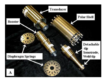
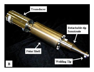
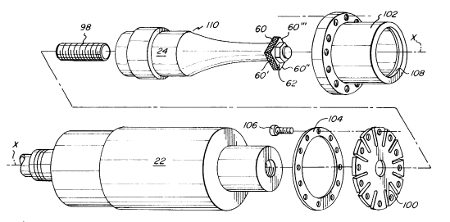
- Figure 1. Ultrasonic metal welders — typical equipment configurations
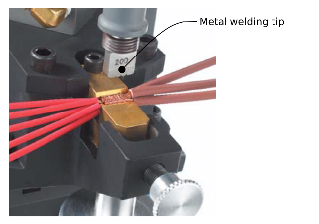
- Figure 2. Replaceable metal welding tip for Wedge-reed welder
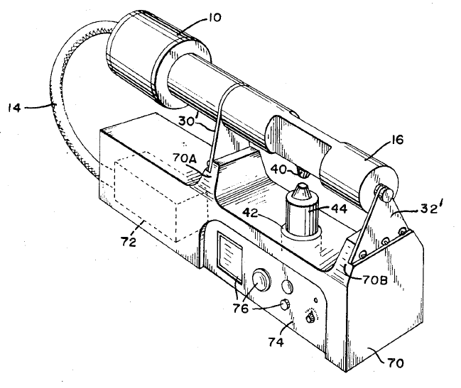
- Figure 3. Lateral drive metal welding horn supported by two vertical members
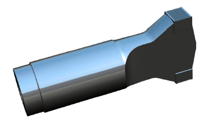
- Figure 4. Lateral drive steel metal welding horn with integral welding surface
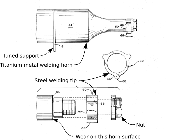
- Figure 5. Lateral drive metal welding horn with replaceable washer tip
- Figure 6. Polar mount for lateral drive metal welder
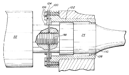
- Figure 7. Rigid mount using flexure diaphragm and restraining collar
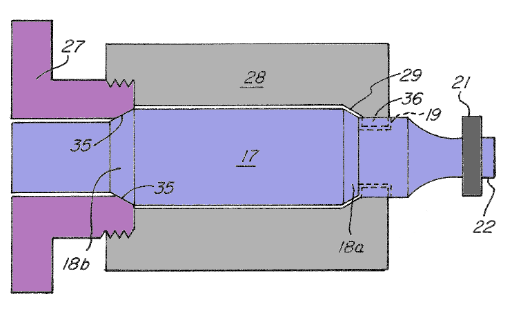
- Figure 8. Rigid mount using nodally mounted shell
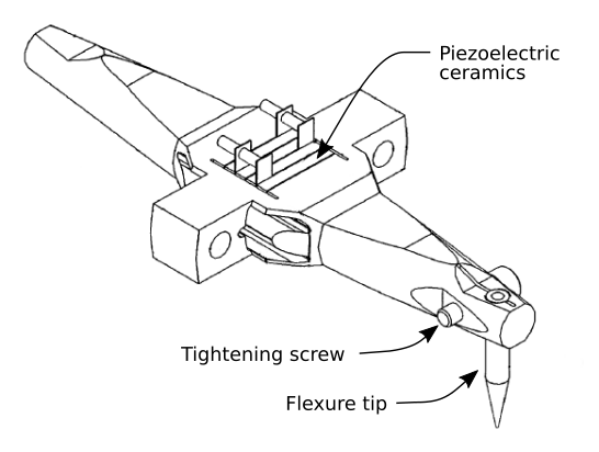
- Figure 9. Microbonder (typically > 60 kHz)
- Figure 10. Polar mount seam welder
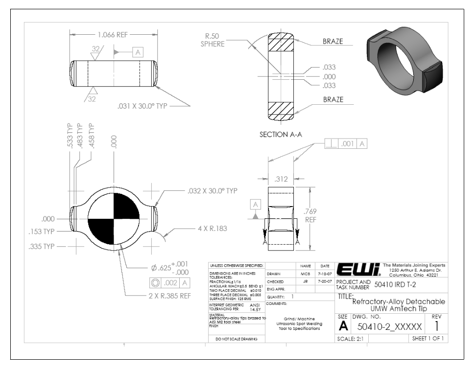
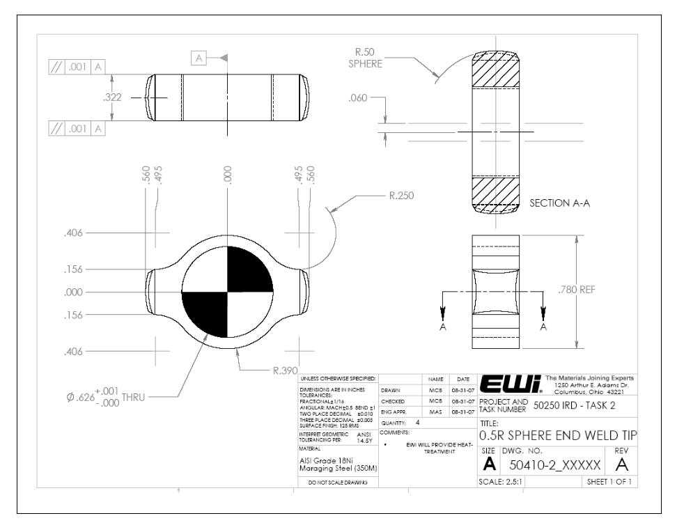
- Figure A1. Dimensions for replaceable metal welding washer tip
- Figure A2. Dimensions for replaceable metal welding washer tip with brazed wear insert
Ultrasonic metal welding is a process of joining two metal parts by applying ultrasonic vibration in a shear (scrubbing) mode. The ultrasonic vibration displaces the surface oxides and contaminates at the interfaces of the two parts, thereby allowing intimate metal-to-metal contact from which the weld occurs. The weld temperature is relatively low and does not involve melting.
Ultrasonic metal welding is most suited for softer metals (aluminum, copper, brass, etc.) although somewhat harder materials (e.g., titanium) can also be welded. Dissimilar materials can be welded (e.g., copper to aluminum) if their hardness is somewhat similar. Ultrasonic metal welding may be used with materials that have high electrical conductivity for which resistance welding is not well suited.
Spot welding
Figure 1 (Al‑Sarraf[1], p. 9) shows two basic metal welding configurations — the Wedge-reed system and the lateral drive system.
|
|
|
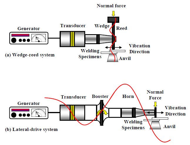
Wedge-reed system
The Wedge-reed system was developed by Aeroprojects (Jones[4] patent 2,946,119, 1960) and is currently used by Sonobond Ultrasonics (Aeroprojects successor). This system's drive consists of a horizontally mounted transducer and wedge horn; The horn is brazed to a vertically-mounted resonant reed. The horn excites the reed in flexure which, in turn, drives a replaceable taper-fit welding tip (figure 2) at the free end of the reed. The required welding force is applied to a mass located at the opposite end of the reed.
Depending on the application, the system can be designed with two colinear opposing reeds, one of which acts as the anvil. These operate at anti-phase thereby effectively doubling the welding amplitude and available power.
This system operates with relatively high force and low amplitude.
|
|
|
Lateral drive system
After developing the Wedge-reed system, Aeroprojects subsequently developed the lateral drive system (Jones[5] patent 3,209,447, 1965). Branson Ultrasonics later developed a lateral drive system with flexurally resonant support members at the antinodes (Shoh[1] patent 3,752,380, 1973, figure 3). Further developments and variations of this system (particularly in the mounting arrangements) are used today.
|
|
|
The horn may be solid (typically hardened steel, figure 4) or may have a replaceable multi-lobed welding tip (Holze[1] patent 3,813,006; see figure 5 and Appendix A; see setup). The ultrasonic stack is often mounted in some type of cylindrical shell (e.g., the polar mount of figure 6) that allows rotation about the stack (polar) axis so that the multi-lobed tip can be properly oriented with respect to the workpiece. Because of its axial symmetry, this arrangement also adapts well to seam welding. (Note — The booster in figure 6a is shown in an incorrect orientation. The stud should be facing the transducer.)
Dual drive
|
|
|
|
|
|
|
||||||||||
|
System comparisons
Weld quality
Weld quality is determined by many factors (importantly, including the process control by the power supply which is beyond the scope of this discussion). One area in which the two systems differ somewhat is the application of the tip motion. In both systems the tip applies shearing motion to the work pieces. However, in addition the Wedge-Reed tip also has some rocking motion due to the flexure of the reed. It is not known to what extent this may impact (posibly improve) the weld quality.
Amplitude collapse?
Clamping force
According to Sonobond's product literature, "The Wedge-Reed system features low vibratory amplitude and high vibratory force, suitable for welding metals." By comparison, "The lateral drive system is characterized by high vibratory amplitude and low vibratory force, appropriate for welding plastics." "Because of [the lateral system's] cantilevered approach, clamping force is applied some distance from the weld, resulting in a bending moment on the coupler that limits static force. This makes the lateral drive system incapable of producing acceptable welds for tinned or oxidized wires and terminals."
Note — A lateral drive system is characterized by the orientation of the horn with respect to the welded part, not the method by which the horn is supported.
Lateral drive support systems
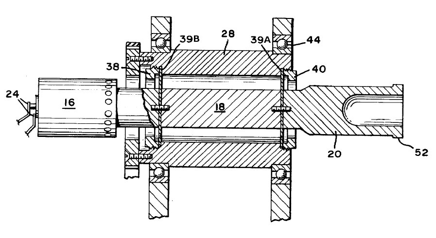
The Shoh patent 3,752,380 (figure 3) shows a lateral drive system where the horn (16) with welding tip (40) is supported between two vertical (flexurally resonant) members (30 and 32). In this arrangement there is no bending moment on the tip. Therefore, the allowed clamping force is only limited by the strength of the support members. (Also see — Jones[5] patent 3,209,447 which addresses the same issue; Roberts[3] patent 6,078,125 discussed here.)
In a lateral drive system where the horn is cantilevered (figure 1, bottom; figure 5), the clamping force will cause the welding tip to deflect vertically and possibly horizontally. Because of the cantilever, the vertical deflection will tilt the tip's welding surface slightly with respect to the anvil (like opening a pair of scissors). The amount of deflection and resulting misalignment will depend on the rigidity of the stack and support structure and also on the clamping force.
For many applications (e.g., tube sealing) this deflection will not cause problems. Also, if the tip is radiused then this may not be a problem since the tip is essentially self-orienting. However, some applications such as wire splicing and wire termination may require more critical alignment. For example, Patrikios[1] patent 8,113,258 states that "the position of the weld tip must be maintained within 3 microns (0.001 inches)" (column 1, line 42). (Note that 3 microns (3*10-6 m) translates to 0.0001 inches, not 0.001 inches, so the specified requirement is unclear. However, either requirement is fairly tight.)
When the horn is cantilevered, there are methods to reduce the horn's vertical deflection.
- Use a very rigid support. For example, Patrinkios[1] patent 5,772,100 (figure 7) show a design with a collar (102) that rests on the horn's node via surface 108. This collar is held stationary so that surface 108 restricts the horn's vertical deflection. The collar is ultrasonically isolated from the horn by a diaphragm (100) at the horn's antinode, similar to the polar mount diaphragm of Shoh[3] patent 3,955,740. (Interestingly, the Partikios patent doesn't site the Shoh patent as prior art.) Like the polar mount, this design doesn't restrict the lateral (axial) movement of the horn. Compared to the polar mount, this design has three additional advantages —
- In the polar mount the booster must be tuned to fit within the length of the shell or, alternately, the shell must be shimmed to fit the existing booster length. Since the Patrikios design does not use a rear diaphragm, its booster length is not restricted. Thus, any off-the-shelf booster can be used.
- In the polar mount the booster diameter is limited by the inside diameter of the shell. Since the Patrikios design does not have a shell surrounding the booster, its diameter is unrestricted.
- Because only one anti-nodal diaphragm is needed, the booster could be eliminated and the stack can be shorter. This assumes that the horn's gain is sufficient to give the required welding amplitude when the horn is driven directly by the transducer.
- On the other hand, if this design is as shown in figure 7 (i.e., where any surface behind surface 108 exceeds the diameter of 108) then the horn can only be replaced by entirely disassembling the collar from the diaphragm. Because the polar mount does not have a collar around the horn, the horn can be easily replaced and any diameter horn can be used.
- In another mounting arrangement the Patrikios[1] patent 8,113,258 (figure 8) restricts both the transverse and lateral deflection of the welding tip. The shell (28) mounts rigidly between two nodes (tapers 18a and 18b) on a full-wave horn (17). This eliminates the somewhat flexible diaphragms of the polar mount and the associated joints which otherwise contribute to the bending compliance.
- Use a stiff material for the horn and/or booster. For example, Young's modulus for steel is almost twice that of titanium. Note, however, that steel is lossy at high amplitudes so this must be considered. Monel might also be used.
- Use a stiff material for the isolation diaphragms. Titanium has normally been used but steel could be substituted if its fatigue life is acceptable. (The original polar mount diaphragms were designed for 10 microns_peak amplitude at 20 kHz. However, this was done without the benefit of FEA for stress analysis (Culp[0]) so the factor of safety is unknown but could be large.)
The above illustrate that very rigid mounts of lateral drive welders are possible. Hence, with proper design to limit deflections, the lateral drive system is not inherently inferior to the Wedge-reed system in its ability to accept high clamping force.
|
||||||||||
|
|
|
|
Clamping force examples
The required clamping force will depend on the application. The following are some selected examples.
Adjustability of welding tip amplitude
The lateral drive system allows horns and boosters of various gains to be used. This allows the amplitude of the welding tip to be mechanically adjusted via these components (rather than through the power supply) so that the power supply can operate at near full power, if needed. The Wedge-reed does not appear to allow these types of alternate configurations.
The welding surfaces are typically (but not necessarily) serrated in order to "grab" the metal workpiece. Problems include adhesion of the welding surfaces to the workpiece ("sticking") and wear of the serrations. These problems may be mitigated in the Wedge-reed system because of its lower amplitude.
Setup
Most lateral drive systems use a replaceable washer tip (figure 4) or a horn with an integral welding surface (figure 4) rather than a vertically oriented tip (figure 3, object 40) that is screwed in, pressed in, or similarly attached. When the welding surface in such systems needs to be cleaned or replaced (e.g., because of sticking or wear), the new welding surface will generally not be initially parallel to the workpiece surface. If this mis-orientation is substantial then the entire ultrasonic stack must be rotated about its axis in order to obtain the proper orientation. (For the replaceable washer tip, this problem can be reduced by using an alignment fixture during installation. Alternately, the tip can be keyed to the horn — see Patrinkios[2] patent 8,113,258.) In contrast, the welding surface of the Wedge-reed tip is always oriented parallel to the anvil so no adjustment is needed when the tip is replaced.
The Wedge-reed welding tip has a male Morse taper that is pressed into a female mating taper in the vertical reed. (A Morse taper is self locking with an included angle of approximately 3°.) During installation the tip can therefore be rotated about its axis to align to the anvil's nest fixture. This allows the fixture to be oriented to the best position with respect to the operator or workpiece. For the lateral drive system, the tip's orientation is fixed with respect to the horn so the nest fixture must be oriented with respect to the fixed tip. This may not be the optimum orientation of the nest fixture.
Accessibility
Throat depth. The Wedge-reed welder has a C-clamp style arrangement between the welding tip and the anvil. The throat depth of this C-clamp can be made quite large (subject only to rigidity considerations) so parts with large lateral dimensions (e.g., sheet parts) can be welded. In fact, if the welding head and anvil were mounted on separate trollies then the workpiece size would be limited only by the travel length of the trolly. In the lateral drive system the lateral part size is limited by possible interference with the horn or the isolation mounts.
Reach. If welding must take place inside a cavity (e.g., at the bottom of a can) then the Wedge-reed welder has an advantage due to its extended reach. (This assumes that the welding surface of the lateral drive system is not designed to vibrate in flexure — e.g., per the microbonder of figure 9.) In theory the reach of the Wedge-reed welder could be increased simply by adding additional flexural half-waves to the reed.
|
|
|
Maintenance and wear
For the lateral drive system of figure 5, the horn is typically made of Ti-6Al-4V. Under high ultrasonic welding loads the horn's surface adjacent to the tip's welding lobe can deteriorate. Branson Ultrasonics has mitigated this problem by changing from Ti-6Al-4V to Ti-7Al-4Mo. Another solution is to substitute a hardened steel horn for the titanium horn.
Alternately, the lateral drive system could use a solid steel horn with an integral welding surface (per figure 4). Then, however, the entire horn must be replaced when the welding surface becomes worn and can no longer be salvaged. The Wedge-reed system does not have these problems since both the tip and reed are made from hardened steel and the taper-fit tip can be easily replaced.
Adaptability
With the addition of bearings and slip rings, the lateral drive system can be converted to a rotary welder (figure 10). This is not possible with the Wedge-reed system.
Weld length.
Tooling
Tooling materials
Good tooling materials should have the following characteristics —
- High wear resistance. High wear resistance is typically characterized by a combination of high toughness and high hardness. These properties must be preserved at the elevated welding temperatures.
- Non-adhesion. The tooling should not stick or bond to the workpieces. (This may depend, in part, on the design of the tooling working surfaces — e.g., the serrations.)
- Reasonable loss. If the tip tooling is integral to the horn (figure 4) then the horn loss must be reasonable at the welding amplitude. (See steel loss.)
Note that the performance of the tooling depends on both the tooling material and its interaction with the workpiece material. Hence, tooling that works well with one workpiece material may not necessarily work well with another workpiece material (see table 1). Regarding hardness, Bloss[1] (p. 96) found that, "The relationship of the required tooling hardness to the welding material hardness is not well defined." For example, consider welding of SS 304 workpieces (table 1) — wrought tungsten (HV 356) had "fair" performance whereas M2 (HV 926; 2.6x hardness) had "bad" performance.
The following section discusses several materials that have been evaluated for the ultrasonic tooling with regard to wear and adhesion. This list of materials is not comprehensive so other (possibly better) materials may also be available.
Table 1 gives a summary of wear and adhesion for various tooling materials that were investigated by Bloss[1] (p. 89).
|
||||||||||||||||||||||||||||||||||||||||||||||||||||||||||||||||
|
Table notes —
- References below are from Bloss[1] unless otherwise noted. See additional information there. Bloss notes, "It is difficult to compare the performance of the tools because of the different materials they were used to weld, the different welding arameters used during the trials, and an inconsistent number of weld cycles applied to each tool."
- HV = Vickers hardnesses; see Bloss table 3, p. 46.
- Italicized materials have shown promise or are used in friction stir welding (FSW) whose requirements are similar to ultrasonic metal welding.
- AISI M2 (5% Mo, 6% W, 2% V) is the most commonly used tooling material because of its high hardness and good wear resistance. However, the vanadium component in M2 readily forms compounds with aluminum workpieces thus promoting tip-sticking. Also, when welding advanced materials such as titanium, M2 tools wear quickly and readily bond to some of the materials. (pp. 28, 70) Hardened to 60-65 RC by quenching from 1200°C; not tempered. (p. 61) HV 926.
- 350M = AISI grade 18Ni maraging steel (18% Ni, 12% Co, 4.8% Mo). Tips constructed of 350M had improved life and wear resistance over M2 while welding AHSS (Advanced High-Strength Steels) and UHSS (Ultra High-Strength Steels). (p. 28) It performed well when welding commercially pure (CP) titanium but tip stickage was a problem with other workpiece materials. (p. 71) Precipitation-hardened at 500°C for 8-12 hours. (p. 61) HV 778.
- Elkon 100W = pure tungsten powder ingots that are pressed and sintered followed by rolling and swaging. (p. 45) The strength of the bond between the tungsten particles was not sufficient. (p. 76) HV 432.
- Wrought-W = pure wrought tungsten with improved strength and ductility over Elkon 100W because of increased deformation and mechanical working. (p. 45) However, pure tungsten still has poor ductility at room temperature (p. 27) so the W‑25Re and W‑La alloys were tried. HV 356.
- W‑25Re = tungsten-25% rhenium. Improved ductility and strength over pure tungsten. (p. 27) Extreme strength and corrosion resistance. (p. 45) HV 509.
- W‑La = proprietary tungsten-lanthanum alloy. It appears to have improved ductility due to the alloying elements and increased forging and swaging. (p. 86) HV 440.
- Tungsten and its alloys are costly and difficult to machine by conventional means. Also, these materials have high density so a full tip would have been too heavy to operate within the allowed frequency range of the ultrasonic welding equipment. For these reasons, small inserts of these materials were brazed onto M2 welding tip blanks. (p. 59) However, the brazed joints were problematic. (p. 90) W‑La inserts were initially brazed with Incusil ABA braze foil but the brazed joints failed during welding. Later inserts were brazed with BNi‑9 (a higher-temperature, higher-strength braze alloy) which proved more satisfactory. (p. 104)
- T1 tool steel (not shown above) was tested but its performance was inferior to 350M tool steel. (p. 28)
- Ceramics have very high hardness but poor toughness. (p. 30)
Sonobond recommended Udimet 700 to Stittsworth[1] (p. 12) for welding "harder" materials (compared to aluminum and copper). The anvil was hardened to HRC 60–64 (p. 30). (Note — this 1973 recommendation may be outdated.)
Branson's tough "ceramic" insert.
Tooling patterns
Knurls. Bloss[1] (p. 27) suggests a knurl pattern (bi-directional) of approximately ½ the material thickness for welding advanced alloys in thicker gauges. The points of the resulting male knurls (pyramids) are flattened. A small radius was added to the bottom of the knurl to improve fatigue properties. (p. 71)
Liesegang[1A] evaluated a pyramidal knurl and a unidirectional knurl for rotary seam welding of titanium. FEA of knurl stresses during welding showed that the averaged von Mises stress with a unidirectional knurl were three times higher than with a pyramidal knurl. (p. 11) The pyramidal tip knurl also gave higher joint strength in the welded specimens. (p. 15)
Textures. Bloss[1] (p. 89) suggests that a non-knurled tool might be possible in situations where high clamping forces are possible (i.e., where sufficient welding power is available so that stalling is avoided). Then the wear could be better controlled and the tip could be periodically refinished. Bloss also reports that dome-shaped tips are often suitable, where the dome radius should be 50 to 100 times the specimen thickness.
Stittsworth[1] (pp. 12, 25) used EDM (electrical discharge machining) to create textured welding surfaces (250 RMS finish). The resulting tips were used in Sonobond's Wedge-Reed equipment to weld thin (~0.13 mm) copper and aluminum strips and wires.
Machining
Some tooling materials may be difficult to machine by "conventional" means. For these materials Bloss[1] used laser machining, grinding, and EDM (electrodischarge machining).
Welding amplitudes
Bloss - 58 microns
Seam welding
As used here, seam welding is defined as a weld in which the horn and workpiece move relative to each other in order to create a continuous or semi-continuous weld. In the typical arrangement the entire ultrasonic stack rotates as a cylindrical disk or cylindrical horn performs the welding. However, a non-rotating horn also may be possible, especially for welding foils. The equipment may be designed so that the horn moves across the workpiece or the workpiece may move under a stationary horn, similar to the operation of a sewing machine. The weld can be narrow or broad.
If the ultrasonic stack must rotate then a lateral drive can be adapted by adding bearings and electrical slip rings (e.g., figure 10). The Wedge-reed can not be adapted.
Note — Seam welding requires that the runout of the welding surface should be kept reasonably small. This is somewhat difficult in the polar mount design of figure 10 because of the tolerance stackup of the interfaces between the horn (52) and diaphragm (39a) and between the diaphragm (39a) and shell (28). The design of figure 8, which eliminates the diaphragms, is more suitable.
|
|
|
|
||||||||||||||||||
|
If the top workpiece is relatively thin (e.g., foils) then the horn's welding surface can either be smooth or may have a light etch or texture pattern. For thicker workpieces the horn's welding surface may need to be more agressive.
Horns
Where that stack is designed to rotate, horns may either be adaptations of conventional resonators or may be designed to vibrate in some flexural mode.
Also see — Ultrasonic Additive Manufacturing (UAM).
Appendix A: 20 kHz metal welding tip dimensions
This appendix shows typical 20 kHz metal welding tip dimensions for the Holze[1] patent 3,813,006 of figure 5 (from Bloss[1]). The tip's knurl pattern and shape of the welding lobe will depend on the particular welding application.
|
|
|
|
|
|