Aluminum properties
Contents
- Figures
- Figure 1. Rotating beam fatigue tests for Al 2024‑T4 and Al 7075‑T6
- Figure 2. Effect of tensile strength on fatigue strength for common wrought aluminum alloys
- Figure 3. Fatigue curves for heat-treatable (2014-T6, 6151-T6) and non-heat-treatable (5052-0, 5052-H36) aluminum alloys
- Figure 4. Q of 24 ST (2024‑T4) aluminum
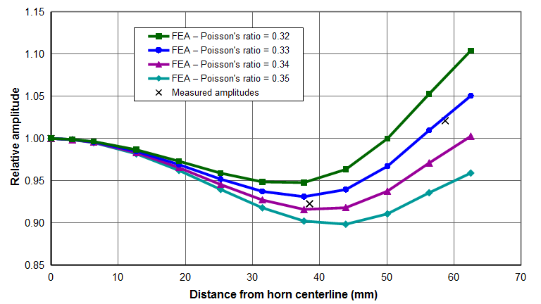
- Figure 5. Ø125mm Al 7075‑T6 spool horn — Effect of Poisson's ratio on axial face amplitudes
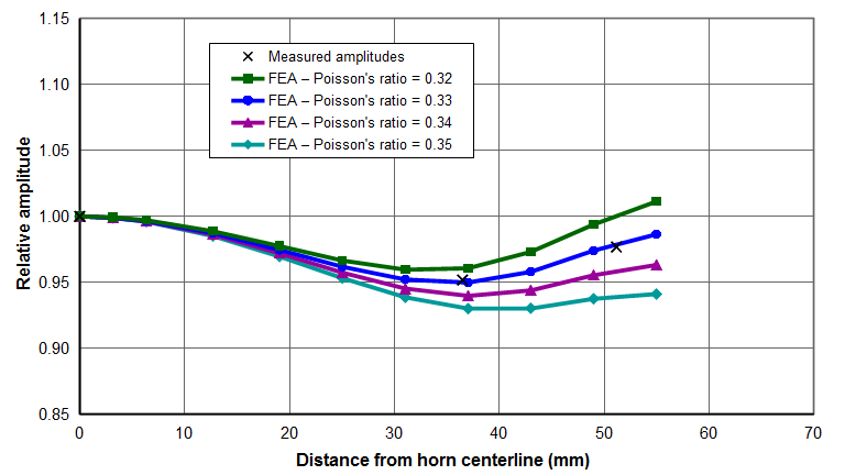
- Figure 6. Ø110mm Al 7075‑T6 spool horn — Effect of Poisson's ratio on axial face amplitudes
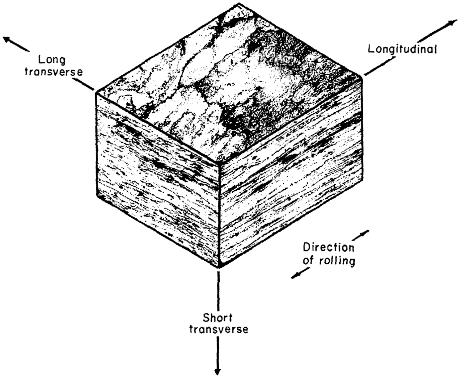
- Figure 7. Directionality in flat rolled Al 7075-T6
- Tables
- Table 1. Best estimates of aluminum material properties
Uses
Because of its relatively low cost and ease of machining, aluminum is often a first choice for ultrasonic resonators where stresses are low and impact/wear/erosion are not important. Uses include —
- Large cylindrical horns
- Large block horns
- Mother horns
- Low gain boosters
- Transducer front drivers
Cross references
A specification cross reference for various grades of aluminum can be found here. This cross reference includes U.S., Canadian, British, French, German, Italian, and Japanese designations.
Common alloys
Aluminum is available in a very large number of alloys. Two commonly used alloys are Al 2024‑T4 and Al 7075‑T6. (The "T" indicates the temper. Various tempers are available which may affect the performance.)
Fatigue
See a general discussion of fatigue.
Most aluminums do not have a true endurance limit. Instead, the negative slope of the S‑N curve becomes more shallow as the number of cycles becomes large. (However, see Varley below.)
The following graphs from Boyer (p. 335) show the fatigue performance of Al 2024‑T4 and Al 7075‑T6 in low frequency rotating‑beam tests. (Original source: Sanders[1], p. 470) The upper band of solid dots is for unnotched specimens whereas the lower band of open dots is for severely notched specimens (Kt > 17). The colored rectangles at the right ends of the data bands are for specimens that did not fail (runout specimens).
|
|
|
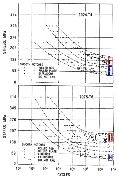
Note that the fatigue performance of the two alloys is very similar. In the unnotched condition both have fatigue strengths in the vicinity of 140 MPa [20 kpsi] at ~109 cycles although Al 7075‑T6 performs somewhat better. In the notched condition Al 7075‑T6 performs somewhat worse.
Boyer[1] (p. 335) notes, "Despite these laboratory data, users discovered that certain aluminum alloys performed decidedly better than others in service when fluctuating loads were encountered. For example, airframe manufacturers determined that fatigue performance of alloy 7075‑T6 was unquestionably inferior to that of alloy 2024‑T3." Boyer does not indicate whether this applies to unnotched or notched or both.
Figure 2 from Juvinall[1] (p. 215) shows the relationship between fatigue strength and ultimate tensile strength for various aluminum alloys. Up to an ultimate tensile strength of about 340 MPa [50 kpsi], the fatigue strength is about 40% of the ultimate tensile strength. However, if the ultimate tensile strength exceeds 340 MPa then the fatigue strength doesn't increase further but, instead, plateaus at about 138 MPa [20 kpsi]. (Note that the two right-most data points have a fatigue strength of about 160 MPa [23 kpsi]; the alloys are not known.) These fatigue strengths are in line with those of Boyer above. (Note that the fatigue strength might be improved above 138 MPa by applying special techniques such as inducing residual compressive stresses. This will depend highly on the type of loading.)
|
|
|
Endurance limit
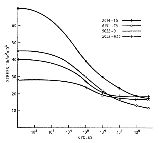
It is often stated that aluminums do not have an endurance limit — i.e., they will ultimately fatigue if the number of cycles is sufficiently great, regardless of how low the alternating stress is. However, figure 3 from Varley[1] (p. 42) suggests that this is not necessarily true. This figure compares the fatigue performance of two heat-treatable and two non-heat-treatable alloys. For the tested alloys this graph shows two important phenomena —
- For the two non-heat-treatable alloys (5052-0, 5052-H36) the fatigue curves flatten when the number of cycles exceed 107; this indicates that these alloys may have an endurance limit. On the other hand, for the two heat-treatable alloys (2014-T6, 6151-T6) the fatigue curves continue to decline even at 5x10⁸ cycles; hence, these materials don't have an endurance limit within the range of tested cycles.
- In figure 3 a material's static strength is the intersection of its curve with the vertical axis (i.e., the strength at zero cycles). It can be seen from this graph that a high static strength does not necessarily predict superior high-cycle fatigue performance. For example, 6151‑T6 has superior static strength compared to either of the non-heat-treatable alloys but is inferior to both at high-cycle fatigue. Based on the slopes of the graphs, it is likely that this inferiority increases as the number of fatigue cycles increases beyond 5x10⁸. Juvinall[1] (p. 215) notes, "As a class, heat-treatable aluminum alloys have lower fatigue ratios and less tendency to approach a true endurance limit than do non-heat-treatable alloys. Recent metallurgical studies [8,20] offer a likely partial explanation: fatigue stressing at room temperature causes overageing of heat-treated alloys."
Based on their high-cycle fatigue performance, one might conclude that the non-heat-treatable aluminums of figure 3 would be superior resonators. However, for ultrasonic applications the static strength also needs to be considered since static strength is needed to resist thread stresses during resonator tightening.
Caution — Varley doesn't give any details of his data. Therefore, it is not known if the graphed data points represent individual failures or averages of multiple failures at a given stress level. If the former is true then the smoothness of these curves seems almost too good to be true, given the typical variability in fatigue lives. None-the-less, further investigation into the ultra-high cycle fatigue range for non-heat-treatable alloys seems warrented.
Note — There are many other non-heat-treatable and heat-treatable alloys beyond those mentioned above. Non-heat-treatable alloys are in the 1XXX, 3XXX, 4XXX, and 5XXX series. Heat-treatable alloys are in the 2XXX, 6XXX, and 7XXX series. However, there are some exceptions. (See Hatch[1], pp. 352-354.)
|
|
|
Quality factor (Q)
Zemanek[1C] measured the Q of 24 ST (now Al 2024‑T4) in a Ø12.7 mm x 3048 mm long rod. The rod was electrostatically driven at low amplitude at longitudinal resonance in a vacuum. The resulting data are shown in figure 4. At 20 kHz the Q is approximately 180,000. (Note that the value on the Y axis must be multiplied by 104 to give the actual Q value.)
|
|
|
Zemanek[1C] (p. 1285) commented that flexural resonances are more highly damped than longitudinal resonances. However, it is not clear if he meant this as an inherent characteristic of the flexural mode or whether this was due to his means of exciting the flexural mode.
Note: Culp[0] tried to measure the Q of Al 7075‑T6 using the full‑wave/half‑wave method with a Ø17.3 mm horn at 20 kHz. However, the results were somewhat inconclusive because the loss measurements at low strains were unreliable. However, at the maximum peak strain of 0.00155 (62 microns_peak), the average net loss of the front half-wave section was about 1.8 watts. This would equate to a Q of about 92000. However, because of the difference in the test methods this data may not be sufficient to conclude that the Q of Al 7075‑T6 is inferior to that of Al 2024‑T4 (above). (Note: although Culp's tests were run in air, the acoustic radiation (i.e., energy transferred to the air) from the end of the horn was assumed to be constant between the initial full‑wave test and the subsequent half‑wave test since both were run at the same amplitude. Therefore, this acoustic radiation did not have any effect on the net power loss.)
Comparison to titanium
For an unspecified titanium with a Q of 27000 under the same test conditions, Culp measured a net loss of 9.7 watts. Thus, based on the limited data from Culp, the loss of Al 7075‑T6 would be about 80% less than the titanium.
Considering Mason's data for Ti-6Al-4V (Q = 20000) and Zemanek's data above (Q = 180,000), the loss of Al 2024‑T4 would be about 93% less than Ti-6Al-4V. However, the strains of Mason's tests were significantly higher than those of Zemanek although it is not known if this would affect the comparison.
Qualitatively, aluminum remains cool where titanium becomes warm or hot under the same conditions. (Of course, aluminum remains cooler, in part, because of its higher thermal conductivity whereby heat is conducted away from the areas of high strain.)
Poisson's ratio
Culp[0] determined Poisson's ratio for Al 7075‑T6 cylindrical stock by comparing the measured amplitudes of a 20 kHz Ø125 mm half-spool horn to those predicted by FEA. Figure 5 shows that the measured "X" data agree most closely with the FEA curve whose Poisson's ratio is 0.33. (In figure 4, each of the "X" data is actually the average of eight amplitude measurements (equally spaced at 45°) around the face of the horn. The variation in these measurements was small so the data is assumed to be reliable.)
Analysis of a 20 kHz Ø110 mm half-spool horn, also made of Al 7075‑T6 cylindrical stock, showed similar results (figure 5a). However, the effect of Poisson's ratio on the face amplitude was not as pronounced.
For comparison, matweb.com gives a value of 0.33 for both Al 2024‑T4 and Al 7075‑T6.
It is interesting that a small change in Poisson's ratio has a significant effect on the relative face amplitudes.
|
|
|
|
|
|
Directionality
Aluminum in the annealed condition that has not been cold worked will have randomly oriented grains and will be isotropic — i.e., its mechanical properties will be uniform in all directions. However, once it has been cold worked (e.g., by rolling, extrusion, etc.) the crystals reorient themselves so that the material is no longer isotropic (see figure 5 from Hatch[1], p. 376). Then the material properties depend on the test direction.
|
|
|
These directional properties can affect tuning. For example, two identical 20 kHz 2‑slotted bar horns were machined. The first horn was machined so that the longitudinal material direction was parallel to the stud axis (i.e., grain direction parallel to the stud axis); the second horn was machined so that the long-transverse material direction was parallel to the stud axis (i.e., grain direction transverse to the stud axis). The axial frequency of the first horn was 125 Hz (0.6%) lower than the second horn (Culp[0]). This indicates that Young's modulus is about 1.3% lower in the longitudinal material direction. The principal nonaxial resonances of the first horn were also reduced compared to the second horn.
The effect of directionality on uniformity is not known.
Best estimates of material properties
|
||||||||||||||||||||||||
|
Table notes —
- Unless otherwise indicated, the properties were determined by Culp[0].
- The fatigue strengths are for unnotched specimens from Boyer (p. 335) (see Fatigue above).
- The properties don't consider the stock type (rod, bar, plate) or directionality.
- For 2024-T3, the material properties were determined by calibrating FEA against one measured horn.
- For 7075-T6 the properties were determined by —
- FEA calibration against measured horn (7 specimens).
- Horn frequency measured on Herfurth piezo shake table without attached transducer (8 samples).
- Full-wave — half-wave measurements (5 samples).
Surface treatments
A number of coatings have been used successfully with aluminum without apparent reduction in fatigue performance. These include soft nickel, soft chrome, and anodizing. Care must be used with hard coatings because these may crack under stress. The resulting cracks may then propagate into the aluminum, causing failure. However, most coatings are acceptable if used in low-stressed regions (e.g., the face).
Etching
The grain direction in aluminum can be checked (either before or after machining) with Keller's etch (1% HF (hydrofluoric acid), 1.5% HCl (hydrochloric acid), 2.5% HNO3 (nitric acid), balance water). For copper-based aluminum alloys (the 2000 series such as 2024) Kroll's Reagent (1% HF (hydrofluoric acid), 12% HNO3 (nitric acid), balance water) is recommended. Both which are available commercially.