Fatigue
Contents
- Fatigue tests
- Fatigue S‑N graphs
- Determining acceptable working stress
- Factors that affect fatigue
- Improving fatigue
- Materials
- Figures
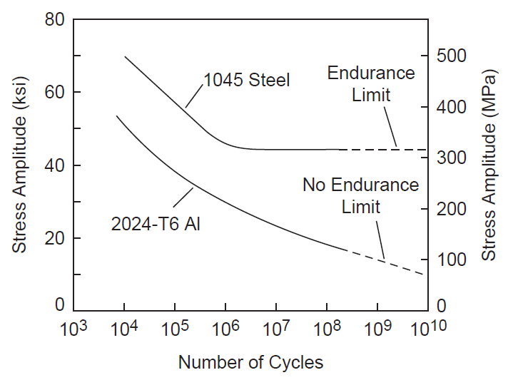
- Figure 1. Comparison of steel and aluminum fatigue behavior
Fatigue is a process where a material (or structure) fails because of progressive crack growth due to repeated cyclic stress. The cyclic stress is usually considerably below the material's yield strength. Fatigue is the predominate failure mode for ultrasonic resonators.
Fatigue is a very complex topic; the literature contains literally thousands of papers. This section will present a limited overview of topics that are relevant to ultrasonic resonator design.
Fatigue tests
Fatigue tests apply cyclic stresses to specimens. In addition, static loads may be simultaneously applied. Each test is stopped when the specimen fails by fatigue or when a specified number of cycles has occurred.
Fatigue tests can be broadly categorized according to the test purpose, test frequency, and load type.
Test purpose
- Material evaluation. These tests determine the fatigue characteristics of a test material. Different specimens may be tested at different stresses so that an S‑N curve can be developed (see below). Alternately, all specimens may be tested at a single stress so that different materials can be compared (although this may produce anomalous results). Fatigue tests of this type use specially designed test specimens.
- Design evaluation. These tests are used to compare the lives of different resonator designs. Because of the cost of the specimens, these fatigue tests are often conducted at only a single stress level.
Test frequency
"Conventional" fatigue tests are conducted at relatively low frequencies, typically around 30 Hz. Such tests are sometimes referred to as Wöhler tests after the early German investigator. (See Juvinall[1], pp. 205 - 206.) Unless otherwise specified, fatigue data from the literature will have been determined from this type of test.
Accelerated fatigue tests are conducted at ultrasonic frequencies. The correspondence to conventional test results is not entirely clear.
Load type
Conventional tests can load the specimen axially, by bending, by rotating-bending, or by torsion. Ultrasonic tests use axial loading almost exclusively.
Fatigue S‑N graphs
The following discussion applies primarily to material fatigue tests rather than design fatigue tests.
When specimens are tested at multiple stress levels, the resulting failure data are plotted on S‑N graphs where S (stress) is plotted on the vertical axis and N (number of cycles to failure) is plotted on the horizontal axis. The horizontal axis is typically a log scale and the vertical axis may be either a linear or log scale. Figure 1 shows a typical S‑N graph.
A fatigue S‑N curve is fitted to the raw failure data. This fatigue curve represents the mean failures (i.e., for a given stress, the life at which 50% of specimens would have survived and, conversely, 50% would have failed).
One parameter that is frequently reported in the literature is the stress ratio \( R \). The stress ratio can account for the effect of static stress. However, for most ultrasonic resonators the static stress will be negligible in comparison to the dynamic stresses. In this case, the stress will be "fully reversed" — i.e., \( R = -1 \) (see here).
The literature will often report fatigue tests where \( R ≠ -1 \) (i.e., tests with a superimposed static stress). Generally, such test results should not be applied to ultrasonic resonators (see here).
Material classification by life
A general characteristic of fatigue is that a specimen's life increases as the cyclic stress is reduced.
Endurance limit
Materials can be classified according to whether they have an endurance limit — i.e., a cyclic stress below which they will not fail even after a very large number of cycles (essentially infinite life). The "very large number of cycles" to which the material must be tested is typically at least 107 (Campbell[1], p. 244) but may be up to 1010 or even higher (Marines-Garcia[1]). (Note that ultrasonic cycles accummulate very rapidly. For example, a 20 kHz aluminum horn that operates 24 hours per day at a 50% duty cycle would need to endure 16 million operational seconds (i.e., 3x10¹¹ ultrasonic cycles) in order to survive for one production year. )
An endurance limit is characterized by a "knee" in the S‑N curve where the curve flattens and becomes parallel to the X axis (number of cycles). Titanium and ferrous materials are presumed to have endurance limits (see figure 1 from Campbell[1], p. 246). The value of the endurance limit depends on many factors (below). If a resonator is made from a material that has an endurance limit then the resonator should generally be designed so that its peak stress is below the endurance limit, after applying an appropriate factor of safety. (If a resonator is expected to have a limited life (e.g., disposable medical resonators) then a higher stress might be tolerated.)
Fatigue strength
Many materials (e.g., aluminum) do not have an endurance limit — i.e., they will eventually fail even at very low stresses. Therefore, resonators made of these materials must be designed for acceptable finite life. Although aluminum does not have an endurance limit, the slope of the S‑N curve becomes more gradual as the stress is reduced (zzz reference) so quasi-infinite life is possible. Materials that do not have an endurance limit are assigned a fatigue strength value — i.e., a stress at which 50% of tested specimens will have failed at a specified number of cycles. For example, matweb.com says that Al 7075-T6 has a fatigue strength of 159 MPa at 5x10⁸ cycles (completely reversed stress). However, this fatigue strength value has limited utility since it is a single point on an otherwise unspecified S‑N curve and, therefore, cannot be used to estimate the life at any other stress.
(Maennig[1] gives a statistical experimental method for determining the number of fatigue cycles corresponding to the fatigue limit, if a fatigue limit actually exists for the particular material.)
|
|
|
Determining acceptable working stress
During the resonator design process the resonator stress should be established (e.g., from FEA). This stress is determined at a reference amplitude, typically one micron peak. For example, the stress might be established as 1.2 MPa at one micron peak. This stress can then be scaled linearly to any other amplitude.
The resonator stress can be used in two manners depending on what parameter has been specified —
- The resonator's amplitude has been specified. If the resonator's amplitude has been determined (e.g., in order to perform a particular application) then the resulting resonator stress can be compared to the material's S‑N curve in order to estimate the resonator's life.
- The resonator's life has been specified. If a certain resonator life is required then the S‑N curve can be used to estimate the maximum resonator stress. Then the maximum amplitude at this stress can be determned. This value is often etched into the side of the resonator.
Fatigue cracks start at microscopic imperfections which are randomly distributed throughout the material. Thus, unlike static tests (such as tensile tests) which have narrow data scatter, fatigue tests often have wide data scatter, even for carefully prepared specimens. The scatter is even worse for "as produced" specimens such as working horns. Thus, the mean S‑N curve (i.e., 50% failure) is not really suitable for design purposes.
Therefore, in order to obtain acceptable life with a reasonable failure rate, the working stress must be reduced below that indicated by the mean S‑N curve. For example, if a 5% failure rate is acceptable then a 5% failure curve must be established. This 5% failure curve can only be established if a sufficient number of tests have been conducted at a number of stress levels. Thus, although a large number of tests would theoretically be needed, this might not be possible because of time, budget, or other constraints. Even where such tests have been conducted, the posted literature often just presents the S‑N curve without the underlying raw data so that the data spread can not be determined. Even worse, much reference literature cites a single fatigue strength value (see above).
Thus, determining an acceptable value for the allowed stress is quite difficult.
Factors that affect fatigue
Laboratory fatigue tests (S‑NL) are conducted under highly controlled ("ideal") conditions. (Here, laboratory fatigue tests are designated as S‑NL to distinguish them from fatigue results that occur under real-world conditions.) The S‑NL tests use carefully prepared specimens. When using S‑NL data to estimate the fatigue of an working resonator, care must be taken to factor in the real-world conditions. Otherwise, the fatigue estimate for the working resonator will be incorrect. This requires that the allowable resonator stress should be reduced compared to S‑NL tests. Unfortunately, estimating the effect of these compounding factors is difficult.
The following factors should be considered when attempting to determine real-world fatigue when using to S‑NL data.
Microstructure
Simply stating the chemical composition (Ti-6Al-4V) doesn't describe the material's microstructure which is affected by method of processing (wrought, rolled, extruded), heat treatment, finishing method, etc. All of these affect fatigue performance.
Processing method
A material may be forged, extruded, rolled, cast, etc.
Heat treatment
Heat treatment depends on atmosphere (air, argon, nitrogen, etc.), temperatures, duration at each temperature during heating and cooling, quenching media (air, water, oil, etc), post processing, etc. These parameters depend, in part, on the size of the part.
For example, consider unnotched Ti–6Al–4V at 107 cycles. In the annealed condition the endurance limit is 510 MPa compared to 700 MPa when solution treated and aged (STA). (Important — the test conditions were not specified. Therefore, these endurance limits should only be used for comparison.)
Titanium's heat treatment will affect the endurance limit. For example, matweb.com gives 510 MPa for generic annealed unnotched Ti–6Al–4V at 107 cycles versus 700 MPa for STA (solution treated and aged). However, see Appendix E for important notched results. (Important: the test conditions were not specified. Therefore, these endurance limits should only be used for comparison.)
Surface conditions
Surface conditions are critical since most fatigue cracks start there.
Surface finish
S‑NL test specimens typically have a finely polished surface finish, often parallel to the specimen's axis. Real-world resonators would not normally receive such care so their lives would likely be shorter than the S‑NL test specimens at the same stress level.
Residual stresses
Residual tensile stresses may reduce the fatigue life. These may result from some machining operations (e.g., harsh electro-discharge machining (EDM), harsh grinding, etc.).
On the other hand Donachie[1] (p. 177) notes, "One further observation about titanium alloys is that fatigue data reported in the literature often may be on material with favorable surface residual stress induced by turning, milling, etc. Fully stress-relieved or chem-milled surfaces probably have fatigue strengths below the reported alloy capabilities, because the latter have been biased upward by the favorable - that is compressive - stresses."
Surface treatments
Surface treatments include platings (which can either be beneficial or harmful) and shot peening (which may be beneficial under certain circumstances).
Stress concentration
S‑NL test specimens are often machined with notch to give a specific stress concentration. This will be indicated if the stress concentration factor Kt is greater than 1.0. The resonator's real-world fatigue would be significantly different than the S‑NL test data unless the two had the same Kt. The ideal situation is where the Kt for the S‑NL test specimens is 1.0 (i.e., no stress concentration).
Machining defects
The real-world resonator may have machining defects (e.g., unblended radii) that are not present in the S‑NL specimen. If these defects are present in a highly stressed region then the allowable stress would have to be reduced.
Test direction
If a material is not isotropic then fatigue may be affected by the direction of the grain relative to the applied stress. For example, see the graph of Boyer[1] (p. 431) below. (Original source: Polmear, I. J., Light Alloys, American Society for Metals, Metals Park, OH, 1981, p. 193)
|
|
|

Frequency
Ultrasonic fatigue tests are typically conducted at 20 kHz or higher. These frequencies are 100—1000 times greater than conventional fatigue tests. This introduces the possibility that the data from conventional fatigue tests (which is most widely available) may not accurately predict ultrasonic fatigue. For example, conventional fatigue tests in corrosive atmospheres may allow sufficient time between cycles for the corrosion to migrate into the fatigue crack whereas such migration may be impeded at ultrasonic frequencies where the time between cycles is short. zzz - reference.
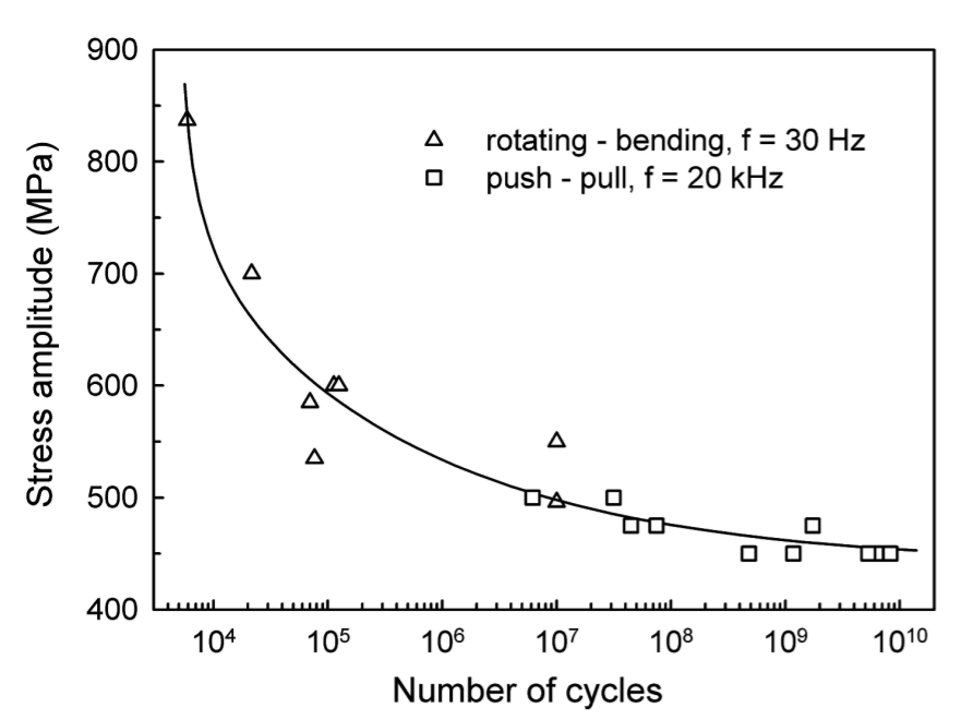
Ultrasonic fatigue tests often show reasonable agreement with conventional low-frequency S‑NL fatigue tests (see below for an example) but this issue is not completely resolved. See Wells[1]. Also see Neppiras[1B] (p. 707) who states, "Measurements have confirmed that the fatigue limit is a function of the operating frequency [comparing ultrasonic results to low-frequency tests]."
Janeĉek[1] tested Ti-6Al-4V (duplex microstructure) at 30 Hz in rotating bending up to 107 cycles and at 20 kHz in tension-compression between 107 and 1010 cycles. The resulting SN curve (figure 2) was smooth regardless of the frequency or testing mode.
|
|
|
Test mode
In axial fatigue specimens the stresses are uniform across the entire cross-section. In rotating beam and bending specimens, however, the stresses are highest on the surface and reduced in the interior. Therefore, these specimens may allow higher stresses than axially stressed specimens where the stresses are uniform across the cross-section. Therefore, to account for axial loading Juvinall[1] (p. 231) suggests reducing the endurance limits S'n of rotating beam and reversed bending tests by about 10%.
Size
Larger parts generally allow lower stresses because there is more material (and potential defects) from which fatigue cracks may start. See Juvinall[1] (p. 231).
Material’s shape
(rod, bar, plate, sheet)
Static stresses
The allowable ultrasonic stress will be reduced when tensile static stresses are present. Such stresses can be significant in long medical probes that are loaded transversely at the free end. Also, significant tensile static stresses are induced at the bottom of a stud hole when a stud is bottomed.
Environment
Adverse environmental factors (temperature, corrosives, cavitation) may reduce the allowed stress. Note that elevated temperatures may arise from heat that is generated within the resonator material due to the ultrasonic vibration (i.e., hysteresis type heating) and from heat that is generated by the ultrasonic process (e.g., heat that is transferred from the melted plastic to the horn's face).
Notch sensitivity
A notch usually reduces a part's endurance limit. For a given notch, a material's conditions may affect its sensitivity to notches. If a material is very sensitive to notches then it will have a large drop in endurance limit compared to the unnotched state. Conversely, if a material is completely insensitive to notches then it's endurance limit will be the same as if the notch weren't present.
For example, a hardened steel is typically more sensitive than than the same steel in a softer condition. Thus, although the harder steel may have a higher endurance limit when no notch is present, the softer steel may prevail when a notch is present. Same true for Ti? STA vs annealed? Ti-6Al-4V vs Ti-7Al-4Mo (based on UTS)?
See Appendix E for the notch sensitivity of Ti–6Al–4V STA.
Improving fatigue
Residual compressive stress
Shot peening
"It should be noted that extension springs are normally not candidates for shot peening." (http://www.centuryspring.com/pdfs/377-381APPENDIX-A.pdf)
Coatings
Nitriding, carburizing, other
Threads
Thread fatigue can be improved by increasing the thread root radius and by adjusting the fabrication method (rolling after heat treating for studs or with thread-forming taps). See details.
Materials
See the following for additional information.